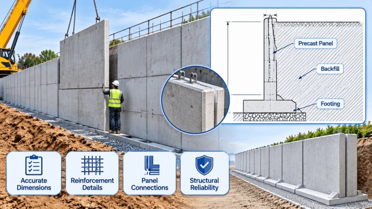
Precast Concrete Retaining Wall Detailing
Precast concrete retaining walls represent one of the most technically demanding elements in structural concrete detailing. From reinforcement scheduling and footing design to panel joint configurations and drainage coordination, every aspect of the shop drawing package must reflect precise engineering intent while accommodating field installation constraints. This presentation provides a comprehensive technical overview of best practices for detailing precast retaining wall systems — covering L-shaped, T-shaped, and cantilever configurations — with guidance on stem and base slab reinforcement, embedded hardware, dowel connections, and weep hole coordination.
Wall Configurations: L-Shaped, T-Shaped & Cantilever Systems
Selecting the appropriate precast retaining wall configuration is a function of retained height, soil bearing capacity, surcharge loading, and site access constraints. Each system exhibits distinct structural behavior and imposes specific detailing requirements on the shop drawing team.
L-Shaped Cantilever Walls
The L-shaped configuration is the most compact precast retaining solution, consisting of a vertical stem monolithically connected to a base slab extending toward the retained soil side. The heel acts as a stabilizing lever through soil overburden weight.
This system is typically employed for retained heights of 3 to 8 feet.
Detailing must address the critical stem-to-base junction, where moment demand is highest, requiring closely spaced vertical bars with adequate lap or mechanical splice transitions. The base slab projection must be sufficient to resist overturning and sliding, with passive pressure resistance factored into the footing design.
T-Shaped (Inverted T) Walls
T-shaped walls extend the base slab both toward the retained fill (heel) and away from it (toe), creating a more balanced overturning resistance.
This configuration is preferred for greater retained heights — typically 8 to 20 feet — where the L-shape base would become excessively long.
The heel slab must be detailed with top and bottom reinforcement to resist upward soil reaction and downward surcharge simultaneously. The toe slab resists upward bearing pressure and requires transverse bottom steel. The stem itself is detailed as a fixed-base cantilever, with vertical reinforcement sized for combined flexural and shear demand. Precasting the full unit in a controlled plant environment ensures tight tolerance control at the stem-base interface.
Segmental & Stacked Panel Systems
For taller walls or phased construction scenarios, stacked precast panel systems allow vertical height to be built up from discrete units.
Each panel connects to the next through cast-in hardware, recessed pockets, or grouted shear keys.
These systems require detailed connection schedules noting panel orientation, stack sequence, leveling pad requirements, and backer rod placement at horizontal joints. Differential settlement between adjacent panels must be accounted for through vertical joint details that allow minor movement without compromising wall integrity or aesthetics.
Structural Design Considerations
Critical Detailing Priorities
Successful retaining wall detailing begins with selecting the correct wall configuration for the site's structural demands. L-shaped walls prioritize compactness, T-shaped walls provide greater stability for taller retained heights, and segmental systems deliver flexibility for large-scale or phased construction projects.
Every precast retaining wall solution is a balance between geometry, soil mechanics, reinforcement detailing, and constructability. Choosing the right system early allows engineers and detailers to optimize stability, fabrication efficiency, and long-term performance.
The structural core of any precast retaining wall shop drawing package is the reinforcement schedule — governing bar size, spacing, cover, lap lengths, hooks, and tie configurations for both the stem and base slab. Detailing must comply with ACI 318 provisions for structural concrete, project-specific geotechnical recommendations, and the engineer of record's design intent.
The stem behaves as a vertical cantilever fixed at the base. Vertical bars on the earth-face resist the primary bending moment caused by lateral earth pressure and hydrostatic load. Bar spacing typically ranges from 6 to 12 inches on center depending on retained height and bar size. The critical section for moment is at the stem-base interface, requiring full development length of vertical bars into the base slab. Horizontal bars in the stem serve as temperature and shrinkage reinforcement, spaced per ACI 318 Section 24.4, and also resist out-of-plane forces from compaction equipment. Hooks at the top of vertical bars are typically standard 90-degree hooks unless wall thickness and cover allow straight embedment. Clear cover for earth-face bars is typically 2 inches minimum; formed face bars use 1.5 inches per ACI 318.
Base slab detailing must address two distinct load conditions: upward soil bearing pressure under the toe and downward surcharge over the heel. Top bars in the heel resist negative moment from retained soil overburden; bottom bars in the toe resist positive moment from upward bearing reactions. Transverse distribution bars are placed at a minimum of 20% of the primary steel area per linear foot. Bar cutoffs must be detailed with adequate extension beyond theoretical cutoff points per ACI 318 development requirements. Base slab thickness is sized to satisfy one-way shear without stirrups where practicable, simplifying plant fabrication.
Reinforcement schedules on precast retaining wall shop drawings must include bar mark, quantity, size (ASTM A615 Grade 60 or A706 Grade 60/80), length, shape code per ACI 315 / CRSI conventions, bending dimensions (A through G), and placement notes. Schedules should cross-reference to plan and section views using consistent mark identifiers. Laps and splices must be explicitly called out — class B tension lap splices are standard unless mechanical couplers are specified. ASTM A706 weldable bars should be noted where welding to embedded plates is required.
All development lengths and splice lengths must be verified against the project-specific concrete compressive strength (f'c) and reinforcement grade as specified on the structural drawings. Do not apply standard tables without confirming design parameters.
Precast fabrication allows tighter tolerances than cast-in-place work. Cover tolerances in precast production are typically –3/8 inch (minus tolerance only) per PCI standards. Shop drawings must reflect nominal cover per structural specifications and note the applicable tolerance. Inspection hold points should be identified for rebar placement verification prior to concrete placement in the plant. All embedded hardware must be coordinated with the rebar layout to avoid conflicts that cause field delays.
Stem & Base Slab Reinforcement Detailing
Stem Reinforcement
Base Slab Reinforcement
Reinforcement Schedule Format
Cover and Tolerances
The connection system is the most critically detailed aspect of precast retaining wall shop drawings. Inadequate connection detailing is a leading cause of RFIs, field delays, and structural nonconformances. Every connection—whether a footing-to-stem interface, a panel-to-panel joint, or an embedded anchor—must be fully detailed with hardware specifications, weld symbols, grout pocket geometry, and installation sequence notes.
Complete connection documentation reduces RFIs, prevents field delays, and protects structural conformance across footing interfaces, panel joints, and embedded hardware.
Footing Connections, Embedded
Components & Panel JointsDetail the connection before it becomes a field problem.
A technically complete precast retaining wall detailing package must address far more than structural reinforcement. Drainage systems, weep hole placement, geotechnical coordination, embedded hardware, reinforcement schedules, and shop drawing standards all contribute directly to long-term wall performance. Since hydrostatic pressure remains one of the leading causes of retaining wall distress and failure, drainage detailing should be treated as a structural design requirement rather than an architectural accessory.
Weep holes provide pressure relief by allowing accumulated water to exit the retained soil mass. Shop drawings should clearly define weep hole locations, dimensions, invert elevations, sleeve materials, and spacing requirements while maintaining alignment with civil drainage design documents.
Drainage aggregate and geocomposite drainage systems must be coordinated with geotechnical and civil requirements to ensure long-term hydraulic performance behind the wall structure.
Comprehensive bar bending schedules are essential fabrication documents that support reinforcement procurement, cutting, bending, placement, and quality verification throughout production.
Project identification, sheet numbering, revision history, scales, and producer certification information.
Applicable codes, material specifications, reinforcement grades, concrete strengths, and fabrication tolerances.
Panel marks, joint layouts, orientation references, and erection sequencing information.
Stem sections, footing interfaces, reinforcement details, drainage systems, embeds, and hardware schedules.
Precast retaining wall shop drawings are fabrication and detailing documents, not design documents. The responsibility of the precast producer is to detail the engineer of record’s design accurately and completely. Any deviation from contract drawings, including reinforcement substitutions, embed relocations, drainage modifications, or dimensional changes, must receive formal written approval before fabrication proceeds. Thorough coordination, disciplined review procedures, and complete documentation remain the foundation of successful retaining wall performance and long-term durability.
Drainage Provisions, Weep Holes & Shop Drawing Standards
Drainage & Weep Hole Coordination
Backfill & Drainage Layer Integration
Reinforcement Schedules & Bar Lists
Shop Drawing Submittal Standards
Shop Drawing Development Workflow
Critical Compliance Reminder
What's Your Reaction?