Deck Sheet Placement Strategy for Phased Construction
In phased commercial and multi-story construction, the sequence in which steel deck sheets are placed is not simply a logistical convenience — it is a structural and coordination decision that directly affects load paths, crane access, shoring requirements, worker safety, and long-term composite performance. Getting the placement strategy right from the outset prevents costly rework, reduces field conflicts, and keeps each phase on schedule without compromising the integrity of work already completed.
Why Placement Sequence Is a Structural Decision
Many project teams treat deck sheet placement as a purely field-driven task — left to the ironworker crew to work out in real time. In phased construction, this assumption creates compounding risk. Each phase introduces temporary loading conditions, partial composite action, and evolving lateral bracing states that the placement sequence must account for explicitly.
Temporary Load Path Considerations
During phased erection, steel beams and joists may carry construction live loads — bundled deck sheets, concrete buggies, pump lines — well before the full structural system is complete. The deck sheet layout determines how those loads distribute across the framing at any given moment.
Placing heavy sheet bundles over mid-span rather than at panel points of joists, for example, can exceed allowable stresses in the temporary condition, even when the final design is code-compliant.
Structural engineers must specify bundle placement zones explicitly in the erection drawings, not leave it as a field assumption. Each phase boundary should be treated as a unique loading stage and checked accordingly.
Partial Composite Action Zones
In composite deck-and-slab systems, shear studs are welded after deck is laid but before concrete is poured. When phasing splits a bay or floor plate, the transition zone between completed composite construction and in-progress framing creates a region of partial composite action that is neither fully shored nor fully engaged.
Deck sheets bridging that zone must be detailed to avoid inducing unintended loads into the finished structure.
The standard practice is to terminate deck runs at the phase boundary beam with positive attachment — typically puddle welds at every flute — and to avoid cantilevering deck sheets across the boundary without explicit engineering review and temporary shoring provisions.
Lateral Bracing State
Steel deck acts as a diaphragm once attached, providing lateral bracing to top flanges of beams and joists. In phased construction, sections of framing may remain unbraced for extended periods. The placement sequence must ensure that deck is attached in a pattern that progressively engages the diaphragm rather than leaving isolated panels without adequate attachment on all four sides.
Phase Boundary Detailing
At every phase boundary, the structural drawings should call out positive deck-end attachment, closure angles or pour stops with verified anchorage, and any required temporary shoring. These details must be coordinated between the structural engineer of record and the deck supplier's engineering team before erection begins — not resolved in the field under schedule pressure.
Documentation & RFI Avoidance
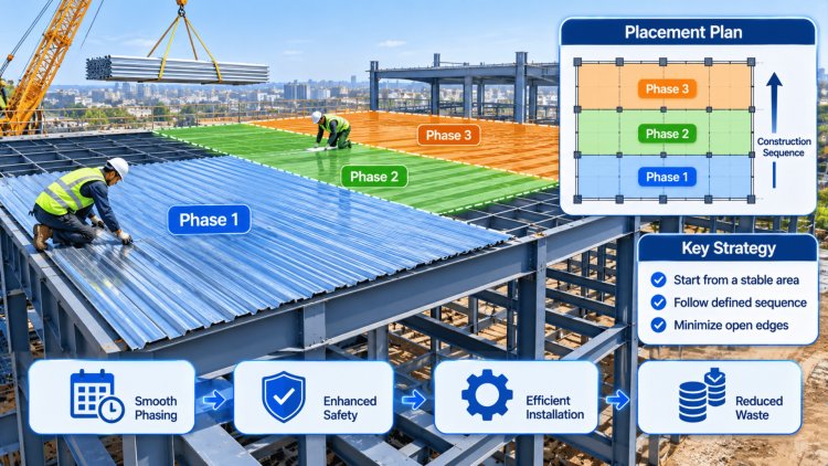
When placement sequence is defined in construction documents, field crews have clear direction and RFI volume drops substantially. Teams that invest in a detailed phasing diagram — showing erection zones, bundle placement limits, attachment patterns, and phase boundary conditions — consistently report fewer structural holds and faster phase-to-phase transitions.
Critical Phasing Verification Checklist
Placement sequence is not simply an erection preference. It is a structural design variable that directly affects temporary load paths, composite action development, diaphragm behavior, worker safety, and project schedule performance throughout the construction process.
The most successful phased deck projects recognize that erection sequence is part of the engineering. When temporary conditions are analyzed with the same rigor as the final structure, risks decrease, RFIs drop, and construction progresses with greater predictability and control.
A well-engineered deck placement strategy for phased construction is built around four interlocking principles. These principles apply whether the project is a three-story office building with two erection phases or a ten-story mixed-use tower with rolling floor-by-floor sequencing.
Core Principles of a Phased Placement Strategy
Deck placement and concrete pouring are typically treated as sequential operations, but in phased construction they frequently overlap—concrete is being poured on a completed phase while deck is still being placed on the next. This overlap is one of the most consequential coordination challenges on a phased steel deck project, and it demands a formal sequencing protocol agreed upon before construction begins.
Wet concrete eliminates any safety margin that temporary friction or partial welding might appear to provide under dry conditions.
Sequencing the Pour: Deck Placement
Relative to Concrete OperationsNo pour until attachment is inspected and documented.
Successful phased steel deck projects are built on planning, coordination, and disciplined execution. The most effective teams resolve sequencing challenges long before crews arrive on site, turning potential field conflicts into documented procedures. When deck phasing, structural checks, crane logistics, and attachment requirements are aligned early, projects move faster, safer, and with significantly fewer disruptions.
Create a formal deck phasing package that clearly identifies erection zones, sheet orientations, pour sequences, temporary shoring, bundle placement restrictions, and phase-transition requirements. This information should exist as a standalone deliverable rather than being buried in general project notes.
Coordinate deck installation activities directly with crane operations and steel erection sequencing. Map every deck zone against future crane picks to identify conflicts before work begins.
Require complete inspection and approval of deck attachment before installation crews advance into subsequent bays. The process should be documented as a project-specific safety and quality-control requirement.
Conduct formal reviews at all phase boundaries and transition conditions. Evaluate differential deflection, concrete containment, pour-stop performance, and structural continuity at every interface.
Establish erection boundaries, pour sequences, and logistics plans early.
Confirm support conditions, attachment requirements, and temporary loading assumptions.
Protect future erection activities from deck placement conflicts.
Verify attachment quality at every phase boundary before advancing operations.
Well-sequenced deck placement is not project overhead—it is a primary driver of safety, schedule certainty, and construction efficiency. Projects that establish dedicated phasing plans, coordinate crane activities, enforce attachment inspections, and formally review interface conditions consistently experience fewer delays, lower RFI volumes, improved field productivity, and stronger project outcomes. The most successful phased deck projects are won during planning long before the first deck sheet is installed.
Practical Takeaways for Your Next Phased Deck Project
Publish a Dedicated Deck Phasing Plan
Build the Crane-Deck Coordination Matrix
Enforce the Attachment-Before-Advancement Rule
Formally Review Every Interface Zone
Phased Deck Success Framework
Project Team Checklist
Final Takeaway
What's Your Reaction?