Roof Deck Coordination with Roof Screens and Equipment Curbs
On commercial roof deck projects, the intersection of structural steel, roofing assemblies, and mechanical equipment is one of the most coordination-intensive zones on any building. Roof screens, equipment curbs, and penetrations introduce concentrated loads, blocking requirements, and sequencing conflicts that — if left unresolved — cascade into costly field changes. This guide addresses the critical coordination touchpoints that architects, structural engineers, and BIM coordinators must manage to deliver a clean, constructible roof deck package.
Why Roof Deck Coordination Is a High-Risk Zone
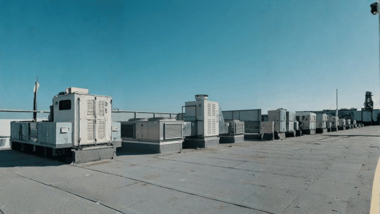
The roof deck level represents one of the most coordination-intensive areas of any modern building. Structural framing, mechanical systems, electrical infrastructure, plumbing penetrations, roofing assemblies, fall protection systems, and architectural screening all compete for the same limited space. A single coordination mistake can ripple through multiple disciplines, resulting in redesign, fabrication delays, change orders, and costly field modifications.
More Disciplines Collide Here Than Almost Anywhere Else
Every rooftop unit, curb, duct, sleeve, conduit, drain, screen wall, and structural member competes for space within the same structural plane.
Why Coordination Breakdowns Occur
Structural Loads
Heavy rooftop equipment introduces concentrated loads that often exceed assumptions made during schematic design.
Penetration Conflicts
Ducts, sleeves, drains, and conduit routes frequently compete with joists, beams, and deck supports.
Sequencing Risk
Equipment selections often lag behind structural procurement schedules, creating coordination gaps.
Equipment Weight Changes Everything
Penetration Conflicts Occur Where Structure Is Most Dense
Assume Extra Blocking
Additional framing and reinforcement are included proactively, increasing upfront cost but reducing future uncertainty.
Field Modification
Waiting for final equipment data often results in welding, cutting, and structural revisions after installation begins.
Coordination Best Practices
✓ Federated BIM reviews
✓ Dedicated penetration plans
✓ Structural capacity validation
✓ Clash detection workflows
✓ Procurement schedule alignment
✓ Multi-discipline signoff process
Most Roof Deck Problems Begin as Coordination Problems
Roof deck failures rarely originate from inadequate deck capacity alone. More commonly, they stem from uncoordinated equipment loads, misplaced penetrations, incomplete mechanical information, and late-stage design revisions. Effective BIM coordination transforms these issues from field problems into digital model reviews.
The Roof Is Where Disciplines Converge
Successful roof deck projects depend on much more than structural calculations. They require continuous coordination between structural, architectural, mechanical, electrical, plumbing, roofing, and construction teams. When equipment loads, penetrations, sequencing, and support requirements are coordinated early, projects avoid costly redesigns, steel revisions, fabrication delays, and field rework while delivering a safer and more reliable roof system.
Equipment curbs are prefabricated or field-built frames—typically 8" to 18" tall—that elevate rooftop mechanical units above the roof membrane, providing a weathertight base and a load transfer point to the structure below. From a structural coordination standpoint, curbs are not just a roofing detail; they are a load path element that must be traced back through the deck, to the joists or beams, and ultimately to the primary framing.
Light-gauge or structural channels welded between joists to support curb base flanges, typically required when curbs fall mid-span. The deck alone is rarely adequate to transfer equipment loads.
When curbs bear directly on a joist, the top chord must be checked for the concentrated load—often requiring a heavier chord or bearing seat modification.
Wood nailers fastened to deck ribs or structural members provide the curb attachment substrate, but must be sized and anchored to transfer lateral and uplift loads, not just gravity.
For very heavy equipment (>5,000 lbs), a W-shape or HSS beam framed between primary members is often the most efficient solution, eliminating complex joist modifications.
Equipment operating weight (not shipping weight—add refrigerant, coil water, and maintenance personnel loads).
Length × width, with direction of airflow affecting clearance requirements.
Full-perimeter bearing vs. point-bearing corner pads.
Spring isolators can change load distribution significantly.
Curb bears directly on joist top chord. Requires top chord capacity check and possible reinforcement.
Curb spans between joists. Requires supplemental channel framing or beam substitution.
Curb spans multiple joists. Requires load distribution analysis and possible joist reinforcement.
The structural design must be based on operating weight, which includes refrigerant, coil water, and maintenance personnel loads.
Issue as separate drawing or clearly tagged on structural roof framing plan.
Show continuous load path from equipment through curb to primary framing.
Confirm clearance between curb and adjacent penetrations or screen walls.
Coordinate nailer/blocking details with roofing manufacturer's warranty requirements.
Equipment curbs are not just roofing details—they are structural load path elements that must be traced from the equipment through the curb, deck, joists or beams, and ultimately to the primary framing. Confirm curb location on the structural grid, verify operating weight against joist or beam capacity, check deck gauge adequacy, coordinate nailer and blocking details, and issue a clear equipment curb framing plan. The quality of curb coordination directly impacts structural performance and roofing warranty compliance.
Equipment Curbs: Structural Requirements and Detailing
Curb Framing Strategies
Supplemental Channel Framing
Joist Top Chord Reinforcement
Blocking and Nailer Assembly
Beam Substitution
Critical Coordination Data Required from MEP
Operating Weight
Curb Size and Orientation
Base Flange Configuration
Vibration Isolation
Curb Coordination Checklist
Load Path Verification
Curb Location Strategies
On Joist
Between Joists
Across Joists
Operating Weight, Not Shipping Weight
Equipment Curb Detailing Requirements
The Curb Principle
Roof screens may appear as simple architectural elements, but structurally they introduce wind-driven lateral loads, complex base connections, and framing interfaces with the deck. Proper detailing and coordination are essential to ensure performance and warranty compliance.
Roof screens act as cantilevered or propped panels subject to significant wind pressures. The lateral load path must be traced from the screen face through the base connection into the deck or framing. Engineers must confirm roof framing can absorb added shear loads, not just gravity.
Improper base connections can void roofing warranties. Base plates welded directly to the deck disrupt membrane continuity. Correct detailing requires bases to bear on structural curbs or nailers above the membrane, with anchor bolts sized for gravity and uplift. Coordination among engineer, consultant, and architect is critical.
Roof screens often lack proper representation in structural BIM models at LOD 300. This creates gaps between architectural and structural teams. Assign clear authorship for screen framing in the BIM Execution Plan and include screens in federated clash detection to verify load paths and base plate locations.
Roof screens demand structural rigor. Wind load paths, base connections, and BIM coordination must be explicitly detailed to prevent failures, warranty issues, and misalignments between design intent and field execution.
Coordination of Lateral Loads & Framing Interfaces
Wind Load Transfer Path
Base Connection Detailing
BIM Coordination Requirements
Key Insight
Every penetration through a roof deck represents far more than a hole in the steel. It is a structural, architectural, roofing, and MEP coordination event that directly affects load paths, diaphragm performance, waterproofing continuity, and project schedules. When penetration planning is deferred to the field, projects routinely encounter cut deck ribs, unapproved framing modifications, inspection delays, warranty concerns, and costly rework.
Pipes, ducts, drains, conduits, sleeves, equipment curbs, and grouped utility penetrations all affect deck capacity, framing requirements, waterproofing systems, and construction sequencing.
Untracked rib cutting, unauthorized deck modifications, oversized openings, and undocumented patch framing frequently compromise diaphragm performance, invalidate assumptions used in structural calculations, and create inspection challenges long after installation.
Structural drawings omit blocking locations while roofing documents assume structural support already exists.
Issue a Roof Blocking & Nailer Plan showing structural intent, anchorage requirements, and geometry controls.
In high-wind environments, blocking withdrawal resistance and anchorage often govern design conditions. Structural calculations must verify that uplift forces can be transferred safely into the supporting structure while maintaining roofing system continuity.
While often viewed as roofing details, deck penetrations and blocking directly affect structural load paths, diaphragm continuity, wind resistance, elevation control, and overall building performance. Proper planning prevents expensive field decisions and preserves both structural integrity and roofing warranties.
Successful roof deck projects depend on disciplined penetration management, explicit framing requirements, coordinated blocking layouts, and clearly defined structural ownership. Projects that document these items early avoid diaphragm compromises, fabrication conflicts, warranty disputes, schedule impacts, and costly field modifications while maintaining a safe and code-compliant roof system.
Deck Penetrations and Blocking: The Details That Sink Schedules
Every Roof Penetration Is A Structural Decision
Why Penetrations Become Project Risks
Penetration Framing Workflow
Field Modifications Create Hidden Structural Risk
Responsibility Gap
Dedicated Structural Plan
Blocking Design Becomes Critical in Exposure C & D
Recommended Coordination Process
Openings and Blocking Control More Than Waterproofing
The Smallest Roof Details Often Create the Largest Delays
Effective roof deck coordination is not a single design task—it is an ongoing process that spans schematic design through construction administration. The following recommendations address the most common failure points and reflect best practices for projects using BIM-enabled workflows on commercial roof deck scopes.
At the start of Design Development, build a matrix that lists every item penetrating or bearing on the roof deck: equipment units, curbs, screens, drains, conduits, and expansion joints.
Steel fabrication lead times—typically 10–16 weeks for commercial projects—mean that joist and beam sizing for equipment loads must be confirmed well before construction documents are issued.
Explicitly scope roof screen structural framing in the BIM Execution Plan (BEP), assigning LOD 300 responsibility to the structural engineer and LOD 200 architectural massing to the architect.
Avoid relying on general notes or roofing details to communicate curb framing and screen base connection intent.
The matrix assigns every item to a responsible discipline with a clear deadline, preventing details from falling between disciplines.
Locking equipment schedules before steel procurement prevents costly field modifications after fabrication.
Formal clash reports logged and resolved with RFI or drawing revision—not informal email threads.
Effective roof deck coordination spans schematic design through construction administration.
Effective roof deck coordination is not a single design task—it is an ongoing process that spans schematic design through construction administration. Establish a roof coordination matrix early, lock equipment schedules before steel procurement, include roof screen framing in the BIM Execution Plan, and issue supplemental structural details for curbs and screens. These recommendations prevent the most common failure modes and ensure that every penetration and bearing item has clear ownership, defined LOD, and coordinated deadlines.
Actionable Coordination Recommendations
Establish a Roof Coordination Matrix Early
• Every roof penetration or bearing item
• Responsible discipline assigned
• Required LOD in BIM model
• Coordination deadline tied to steel procurementLock Equipment Schedules Before Steel Procurement
• Preliminary equipment schedule from MEP
• Confirmed curb sizes
• Operating weights (not shipping weights)
• Prerequisite for structural 50% CD submissionInclude Roof Screen Framing in the BIM Execution Plan
• LOD 300: Structural engineer responsibility
• LOD 200: Architectural massing
• Federated model review at 75% CDs
• Attendance: structural, MEP, roofing consultant, BIM coordinatorIssue Supplemental Structural Details for Curbs and Screens
• Dedicated Roof Equipment Framing Plan
• Separate from main roof framing plan if complex
• Show all curb locations
• Show supplemental channel framing
• Show nailer/blocking assemblies
• Show screen base plate locationsRoof Coordination Matrix Template
Item
Discipline
LOD
Deadline
Status
RTU-1 Curb
MEP
LOD 300
50% CD
Open
Roof Screen S-1
Structural
LOD 300
75% CD
Open
Roof Drain D-1
Plumbing
LOD 300
60% CD
Open
Expansion Joint EJ-1
Architectural
LOD 300
75% CD
Open
Conduit Penetration P-1
Electrical
LOD 300
60% CD
Open
Coordination Timeline
Establish roof coordination matrix with all penetrations and bearing items.
Lock equipment schedules before steel procurement. Issue preliminary structural details.
Federated BIM model review focused on roof level. Resolve all clashes formally.
Issue dedicated Roof Equipment Framing Plan. Reference in structural notes.Common Failure Modes Prevented
Undefined Ownership
Late Equipment Changes
Informal Clash Resolution
Coordination Is an Ongoing Process, Not a Single Task
The Coordination Principle
What's Your Reaction?