Precast Parking Garage Detailing: Double Tees, Spandrels & Structural Framing
Precast concrete parking structures represent one of the most technically demanding disciplines in structural detailing. From double tee framing grids to complex beam-tocolumn connections, every element must be coordinated with precision — integrating structural performance, drainage, expansion, and erection sequencing into a cohesive set of shop drawings and BIM models.
Understanding Precast Structural Systems & Framing Arrangements
The Precast System Logic
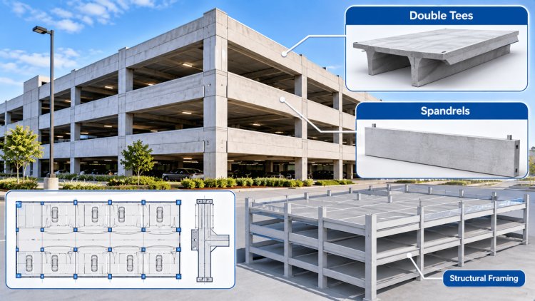
Precast parking garages rely on a fully integrated gravity and lateral system assembled from factory-fabricated components. The structural logic flows from columns up through beams and spandrels, then across double tee floor and roof members. Understanding how load paths interact at every connection is fundamental to producing accurate shop drawings and clash-free BIM models.
Lateral resistance is typically provided by shear walls, moment frames, or a combination — all of which must be coordinated with the diaphragm behavior of the double tee field.
Double Tee Floor & Roof Framing
Double tees (DTs) are the workhorse of precast parking framing. Standard widths range from 10 ft to 15 ft, with stem depths varying from 24" to 34" depending on span. Roof tees are typically lighter-gauge with shallower sections. Key detailing considerations include:
Bay spacing and bearing length on inverted tee beams or ledger beams (minimum 3" bearing is standard)
Flange-to-flange weld plates (standardized at PCI-recommended intervals) for diaphragm continuity
Camber allowances and differential camber between adjacent tees — critical for traffic surface smoothness
Topping slab coordination (topped vs. untopped systems) and their effect on connection design
Roof DT slope (typically 1.5% minimum) for positive drainage away from drain points
Framing Grid
DT bays are typically arranged on a 60 ft module with 30–34 ft spans. Grid coordination must account for ramp geometry, stair/elevator cores, and expansion joint locations.
Drainage Slopes
Floor drainage is achieved by sloping the supporting beams (not the tees themselves) or by varying DT seat elevations. A 1.5%–2% cross slope is standard across traffic aisles and stalls.
Spandrel & Interior Beams
Inverted tee (IT) beams carry DT stems at the interior bays. L-shaped ledger beams are used at ramps and special conditions. Beam depths must clear ramp headroom requirements.
Column Lines
Precast columns are typically 18"×18" to 24"×24" and are designed with corbels or hidden steel haunches to receive beam reactions. Column splice locations are carefully coordinated with erection equipment reach.
Spandrel beams, columns, wall panels, and their connections must transfer gravity, lateral, and torsional forces while accommodating volume-change movements from creep, shrinkage, and thermal effects. Precise detailing of bearing pads, grouted connections, weld plates, and embeds is essential to precast parking structure performance.
Resolve torsion, facade detailing, drainage, bearing pads, grout pockets, and embed schedules across structural, shop, and erection drawings.
Spandrels, Columns, Wall Panels
& Connection DetailsCoordinate every spandrel, bearing, embed, and connection before fabrication.
Beyond individual member detailing, the precast parking structure must function as a coordinated system — managing water, accommodating movement, and acting as an integrated structural diaphragm. These system-level details are where coordination errors are most costly.
Water, movement, and lateral load all cross member boundaries — which is why these system-level details are where coordination errors are most costly.
Drainage Slopes, Floor Openings, Expansion Joints & Diaphragm Coordination
Erection drawings are the field-facing documents that guide the precast installer from first piece to final closure. A complete, well-organized erection drawing set for a parking structure includes:
**Piece mark plans:** Every column, beam, spandrel, DT, and wall panel assigned a unique mark tied to the piece schedule
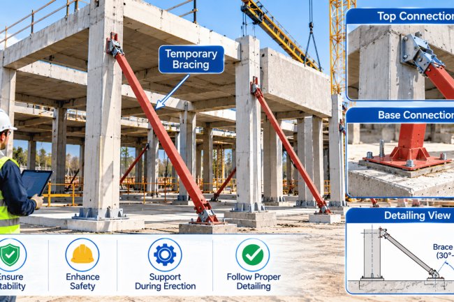
**Erection sequence notes:** Order of piece installation, temporary bracing requirements, and hold points for field welding or grouting
**Bearing and seat elevations:** Tabulated at each support point, accounting for camber, drainage slope, and topping thickness
**Connection details:** Referenced from detail sheets — weld plate types, shim requirements, grout pocket dimensions, and field weld symbols
**Embed schedules:** Cast-in anchors, insert plates, and hardware cross-referenced to both shop and erection drawings
**Tolerances:** PCI MNL-135 erection tolerances noted for critical dimensions — particularly column plumb, beam seat elevation, and DT bearing
BIM modeling has become standard practice for complex precast structures. A well-executed precast BIM model for a parking garage provides:
Automated checking for DT stem vs. beam flange conflicts, embed vs. rebar interference, and mechanical vs. structural penetration conflicts
Accurate piece counts and concrete volumes for estimating and procurement
4D sequencing models that allow the erection contractor to plan crane picks and staging before mobilization
Parametric models in Revit or Tekla Structures can generate piece drawings, elevation views, and schedules directly from the model, reducing manual drafting errors
Linked models allow early identification of conflicts between precast structure and mechanical, electrical, and plumbing systems
PCI MNL-135 (Tolerance Manual for Precast and Prestressed Concrete) and ACI 117 set the governing dimensional tolerances that must be reflected in both shop drawings and BIM model clearances.
Obtain EOR-issued design drawings, connection force tables, diaphragm force diagrams, and volume change calculations before beginning shop drawing production. Resolve all RFIs before detailing begins.
Build the parametric 3D model from column bases up — columns, beams, spandrels, then DTs. Assign piece marks, embed locations, and connection hardware in the model before extracting drawings.
Generate piece drawings, embed schedules, erection plans, and connection details. Cross-reference all documents and confirm that bearing elevations, slope strategies, and expansion joint details are consistent across all sheets.
Submit for EOR review and contractor coordination. Address all comments, confirm erection sequence with the installer, and re-issue for construction. Field RFIs during erection should be tracked and resolved with formal sketch supplements.
Erection Drawings, BIM Coordination & Structural Shop Drawing Best Practices
What Erection Drawings Must Communicate
BIM Modeling for Precast Parking Structures
Clash detection
Quantity extraction
Erection visualization
Drawing automation
Coordination with MEP
Structural Shop Drawing Workflow
Structural Design Coordination
BIM Model Development
Shop & Erection Drawing Production
EOR & Contractor Review
What's Your Reaction?