Light Gauge Steel Staircase Detailing: Stringers, Landings & Structural Connections
A comprehensive technical guide for structural engineers, detailers, and fabricators working with cold-formed steel (CFS) staircase systems. From stringer configurations and landing support details to guardrail integration and fabrication-ready shop drawings, this presentation covers the full scope of LGS staircase detailing — with a focus on code-compliant, buildable, and coordination-ready documentation.
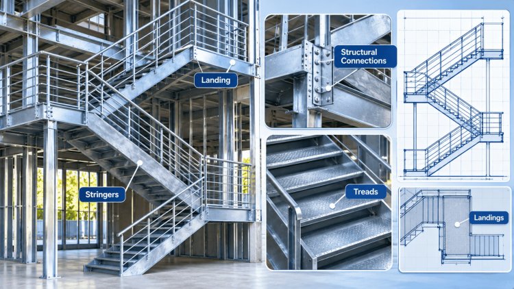
LGS Staircase Systems & Stringer Configurations
Light gauge steel staircases are engineered assemblies typically built from cold-formed steel (CFS) members — most commonly C-channels, track sections, and built-up box sections. Understanding the system type and stringer configuration is the foundation of all detailing work.
Common LGS Staircase System Types
Open-Riser Stringer Systems
Stringers run parallel to the stair slope with no enclosed riser. Treads are attached directly to stringer flanges using clip angles or bent tabs. Common in utility and secondary egress stairs.
Closed-Riser Pan Systems
Steel pans welded or screwed between stringers form the riser-and-tread assembly. Pans are filled with concrete or gypsum to meet fire and load requirements. Typical in commercial multi-story applications.
Mono-Stringer (Center Stringer)
A single built-up box stringer runs along the center of the stair. Treads cantilever to both sides. Requires careful torsion analysis and robust end connections to floor structure.
Prefabricated Modular Stairs
Factory-assembled CFS stair modules shipped to site and bolted to structure. Require precise anchor bolt layouts and coordination with structural openings in the floor framing plan.
Stringer Framing & Section Selection
Stringer depth, gauge, and section type are governed by span, load, and deflection limits. Key detailing considerations include:
**Member selection:** Stringers are typically C-sections (350S or 600S series) or built-up box sections from back-to-back C members. Minimum 18-gauge for residential; 14–16 gauge for commercial applications.
**Stringer slope:** Inclined members must be detailed with plumb cuts at top and bottom bearing points. Cope depths, block-out dimensions, and bearing lengths must be explicitly called out in shop drawings.
**Lateral bracing:** Stringers are susceptible to lateral-torsional buckling. Intermediate bridging, cross-bracing, or blocking between stringers must be spaced per AISI S100 requirements — typically not exceeding 4 to 6 feet on center.
**Web stiffeners:** Required at bearing points and concentrated load locations. Stiffener sizing and attachment (screw pattern or weld) must be detailed at both the top landing connection and the bottom slab/floor bearing.
**Deflection limits:** Live load deflection is typically limited to L/360. Stringer camber or pre-deflection requirements should be noted on fabrication drawings.
All stringer designs must comply with AISI S100 (North American Specification for CFS) and applicable IBC chapter requirements for means of egress stairs.
Precise detailing of individual stair components and landing framing is critical for both structural performance and code compliance. Each element must be coordinated with the overall staircase geometry, the floor framing system, and the architectural finish requirements.
Verify stair geometry, reinforce shaft openings, size landings for code loads, and explicitly detail every stringer, wall, and deck connection before fabrication.
Riser, Tread, Landing
& Opening DetailsDetail the tread, riser, landing, and opening as one coordinated system.
The structural connections between the staircase and the building's floor framing system — combined with properly integrated guardrail and handrail assemblies — define both the safety performance and the code compliance of any LGS stair installation. These elements must be fully detailed, not simply noted.
The upper stringer end bears on a structural header or rim track in the floor framing. A welded seat angle or bolted end plate transfers vertical and horizontal loads.
The lower stringer end typically bears on a concrete slab or CMU wall via a base angle or embedded plate. Where it bears on a CFS wall, full stud blocking and load path continuity to the foundation must be shown.
Both top and bottom connections must include lateral restraint details to prevent out-of-plane movement of the stringer.
Where the stair connects to concrete structure at one end and CFS framing at the other, details must account for differential settlement and shrinkage.
Verify stair width, headroom clearance, and landing dimensions against architectural drawings before beginning detail production.
Identify all finish materials — tile, carpet, nosing — that affect structural reveal dimensions and tread/riser geometry.
Obtain confirmed header and trimmer member sizes from the EOR before detailing opening reinforcement.
Confirm design loads:
All deviations from the structural drawings must be RFI'd and resolved before fabrication.
Stair shafts commonly contain fire suppression piping, conduit, and ventilation.
Coordinate stringer depth and opening reinforcement framing with MEP routing early to avoid costly field modifications.
Use a formal RFI log to track all coordination questions between the stair detailer, EOR, architect, and MEP engineer.
Never assume — document every design decision that affects fabrication.
Structural Connections, Guardrails & Coordination
Staircase-to-Floor Framing Connections
Top Landing Connection
Bottom Bearing Connection
Lateral Restraint
Differential Movement
Guardrail & Handrail Integration
Coordination with Architectural & Structural Documents
Architectural Coordination
Structural EOR Coordination
MEP & Fire Protection
The final deliverable of the LGS staircase detailing process is a complete, fabrication-ready shop drawing package. These drawings must communicate all dimensional, material, and connection information needed for the fabricator to cut, assemble, and deliver the stair without returning to the engineer or detailer for clarification.
Every member, cutout, hole, and bearing surface is fully dimensioned. No implied or assumed dimensions.
Gravity and lateral load paths are traceable from tread to stringer to floor framing on every connection detail.
AISI S100, IBC chapter and section references cited on the drawing set. Egress stair dimensions verified against IBC 1011.
Architectural, structural, and MEP coordination confirmed and documented before the first fabrication cut is made.
"A shop drawing that requires a phone call to interpret is an incomplete shop drawing. Build it on paper before you build it in steel."
Investing time in thorough, coordinated LGS staircase shop drawings pays dividends at every downstream stage — fewer RFIs during fabrication, faster field installation, reduced punch list items, and a final assembly that performs exactly as the structural model predicted. For stair detailers and fabricators alike, the shop drawing package is the product.
Fabrication-Ready LGS Stair Shop Drawings
What a Complete Shop Drawing Package Includes
Key Quality Benchmarks for LGS Stair Shop Drawings
Dimensional Completeness
Load Path Clarity
Code Traceability
Coordination Sign-Off
What's Your Reaction?