CNC Data for Light Gauge Steel: How Digital Fabrication Files Improve Manufacturing Accuracy
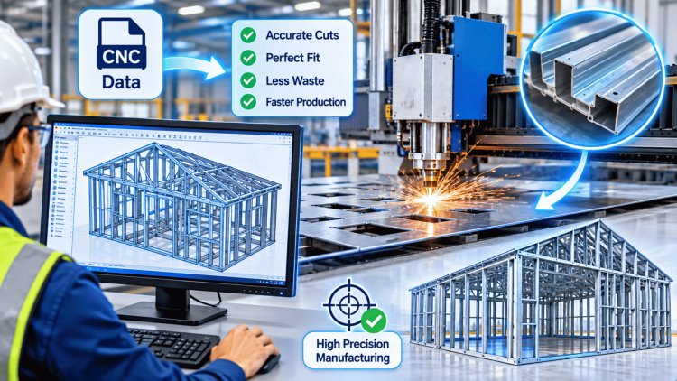
In light gauge steel (LGS) manufacturing, the journey from a structural design to a finished, field-ready panel begins with one critical step: generating accurate, machine-readable CNC fabrication data. These digital files drive the automated roll-forming equipment that cuts, punches, notches, and labels every cold-formed steel stud, track, and header on the production floor. When done correctly, CNC data eliminates manual measurement, reduces human error, and ensures that every component conforms precisely to engineering specifications — from first stud to final delivery.
From BIM Model to Machine-Readable File
The digital fabrication pipeline begins in a BIM or CAD environment — typically software such as Tekla Structures, FRAMECAD Structure, or similar LGS-specific design platforms. Engineers model every stud, track, header, and bridging element with full geometric and parametric data. Once the structural model is complete and coordination-cleared, the software extracts component-level fabrication data and translates it into the formats that roll-forming machines can interpret directly.
BIM / Structural Model
Fully coordinated 3D model with member geometry, section properties, hole patterns, and assembly logic defined at the component level.
Data Extraction & Translation
Software exports parametric data into structured fabrication formats — CSV files, proprietary machine scripts, or XML-based production datasets — stripping non-manufacturing metadata.
Machine-Readable CNC File
Validated, format-specific files are queued to the roll-forming controller, driving automated cutting, punching, notching, and label printing without manual re-entry.
What the CNC File Contains
A fully populated LGS fabrication file encodes far more than a cut length. Each record typically includes: member ID and panel/frame reference, section profile and material gauge, cut length to the nearest millimeter, hole punch locations (service penetrations, fastener patterns, and anchor bolt holes), notch and cope geometry at member ends, and label/marking data for field identification. This density of information is what allows a single file to drive a fully automated production run from material coil to labeled component.
CSV and Proprietary Formats
The most universal exchange format for LGS CNC data is the structured CSV file, where each row represents one member and each column maps to a specific fabrication parameter. CSV files are human-readable, easily audited in spreadsheet tools, and compatible with most machine controllers via import mapping. Beyond CSV, manufacturers increasingly rely on proprietary formats native to their roll-forming platform — .frd files for FRAMECAD, .hwk or machine-specific XML for Howick, and Scottsdale's own production data schema. Each format encodes the same core fabrication parameters but structures them according to the machine controller's input requirements.
CNC data files must be precisely matched to the capabilities and input specifications of the target roll-forming machine. The three dominant platforms in LGS manufacturing—Howick, FRAMECAD, and Scottsdale—each offer high-speed, fully automated production but differ in their controller architectures, file formats, and the specific operations they support. Understanding these distinctions is essential before sending any file to production.
Validate controller format, column conventions, and fabrication capabilities early to protect throughput, traceability, and field installation accuracy.
Machine Compatibility &
Fabrication OperationsMatch CNC data to the machine before it reaches the line.
The most consequential risk in LGS digital fabrication is not the roll-forming operation itself — it is the data pipeline that feeds it. Errors introduced during BIM export, format translation, or file preparation propagate silently through production, resulting in incorrectly punched members, wrong-length cuts, or mislabeled components that only surface during panel assembly or on-site installation.
A robust pre-production QA workflow should address each layer of the data pipeline systematically.
First-article inspection is the highest-value QA activity in LGS fabrication. A five-minute physical check of the first member from each new file can prevent an entire production run of nonconforming components from reaching the assembly floor.
Preventing Data Translation & Fabrication Errors
Common Sources of Data Translation Error
Quality Assurance Before Production Release
When CNC data generation is fully integrated into a structured manufacturing workflow, the benefits extend far beyond improved cutting accuracy. Automated Light Gauge Steel fabrication creates a repeatable, traceable, and highly efficient production ecosystem that improves quality, increases throughput, reduces waste, and strengthens project delivery performance across every stage of manufacturing.
CNC-controlled equipment achieves dimensional tolerances that are difficult to maintain through manual fabrication methods. Consistent member lengths, punching locations, and connection details reduce cumulative dimensional variation and improve assembly precision.
Automated roll-forming and punching systems eliminate repetitive manual operations, enabling significantly higher production rates while maintaining consistent product quality throughout long manufacturing runs.
Fabrication errors create direct costs through material waste, production downtime, and corrective activities. Pre-validated CNC data significantly reduces these risks before material enters the manufacturing process.
Every manufactured component can be linked directly to BIM objects, fabrication records, production files, and quality-control history, creating a complete digital thread throughout the project lifecycle.
Validate machine-specific requirements, units, mappings, and parameter conventions before introducing new fabrication files into production.
Structural audits, parameter verification routines, and first-article inspections should be treated as mandatory quality controls.
Reduce manual data handling wherever possible through integrated software ecosystems and documented transfer procedures.
Fabrication files require revision control, approval workflows, change management, and traceability equal to structural drawings.
Automated fabrication workflows are not simply a faster way to produce Light Gauge Steel components—they represent a fundamental shift toward controlled, repeatable, and data-driven manufacturing. Organizations that combine disciplined CNC data management, BIM integration, structured quality controls, and traceable production processes consistently achieve higher quality, better productivity, lower waste, and more predictable project delivery outcomes across every fabrication cycle.
Benefits of Automated Fabrication Workflows & Key Takeaways
Dimensional Consistency
Production Throughput
Reduced Rework & Waste
End-to-End Traceability
Automated Fabrication Workflow
Key Takeaways for LGS Fabrication Teams
Final Manufacturing Insight
What's Your Reaction?