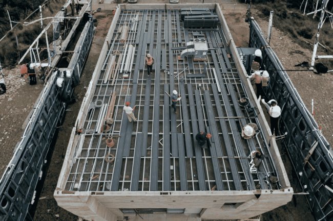
How Steel Deck Supports Lateral Load Transfer
Steel deck is far more than a passive surface for supporting gravity loads — it is a critical structural membrane that collects, transfers, and distributes lateral forces from wind and seismic events to the building's vertical resistance system. Understanding how this mechanism works is essential for structural engineers and steel-deck detailers who must design and detail diaphragms that are both efficient and codecompliant.

The Diaphragm Concept: Steel Deck as a Structural Plane
A steel deck diaphragm is not simply a roof or floor surface. When properly connected, it behaves as a structural system that transfers lateral forces throughout the building.
Think of the Diaphragm as a Giant Horizontal Beam
How Forces Travel
Why Detailing Controls Performance
A deck system can be fully adequate for gravity loads yet still fail diaphragm requirements if fastener spacing, side-lap connections, collector details, or perimeter attachments are not properly detailed.
Every Fastener Is Part of the Load Path
The diaphragm only performs when all components work together. Deck-to-frame attachments, side-lap fasteners, collectors, and edge members are not secondary details. They are essential structural elements that create a continuous path for lateral force transfer.
Wind and seismic forces must travel through a continuous, clearly defined load path from their point of application to the foundation. Steel deck diaphragms form a critical horizontal link in that chain. [web:351][web:352]
A diaphragm should be treated as part of the lateral force-resisting system, not as isolated roof or floor sheathing. Deck fasteners, collectors, chords, openings, and vertical elements must work together as one uninterrupted load path. [web:352][web:357][web:358]
The governing question at every stage is simple: where does the lateral force enter, which element receives it next, and how is it transferred safely to the foundation? If any link is undefined, discontinuous, or under-designed, the load path is incomplete.
Load Path: From Cladding to Core
The Detailing Principle
The shear capacity of a steel deck diaphragm is not just about panel thickness or profile — it is critically determined by the type, quantity, and layout of fasteners at supports, sidelaps, and perimeter edges. SDI DDM04 and AISC Design Guide tie capacities directly to fastening configurations.
At each bearing line, deck attaches to framing with puddle welds, PAFs, or screws. Puddle welds (5/8" arc spot) are common. Spacing patterns like 36/7, 36/4, 36/5 denote deck width and fastener count per sheet per support. Closer spacing increases shear resistance significantly.
Sidelap fasteners tie overlapping flanges of adjacent sheets. Options include screws (#10, #12), button punches, or welds. Screw spacing (12", 18", 24" o.c.) is a primary variable in diaphragm tables. Reducing spacing is often the most economical way to increase capacity without changing gauge.
At diaphragm boundaries, deck forces transfer into chords and collectors. Methods include continuous angle-to-deck welds, clips, or welded shear tabs. These connections carry concentrated loads and require coordination between engineer and detailer to ensure constructability and adequate capacity.
Fastening patterns are as critical as deck thickness. Properly specified support, sidelap, and perimeter connections ensure diaphragm shear capacity meets design demands and aligns with SDI and AISC standards.
Fastening Patterns and Their Role in Diaphragm Capacity
Support Connections (Deck-to-Frame)
Sidelap Connections (Panel-to-Panel)
Perimeter / Edge Connections
Before lateral forces can be distributed to shear walls, braced frames, or moment frames, the diaphragm must be classified as flexible, rigid, or semi-rigid.
A diaphragm can satisfy code-required shear strength and still exhibit excessive in-plane deflection. Serviceability must be verified independently using diaphragm stiffness, fastener slip, shear deformation, and chord elongation effects.
The diaphragm classification determines how lateral forces are distributed, how torsion is evaluated, what analysis methods are required, and how detailing must be executed. Correct classification is the foundation of both strength and serviceability performance.
Diaphragm Flexibility Classification & Design Implications
The Diaphragm Classification Compass
BehaviorDeflection Control Measures
Strength ≠ Acceptable Performance
Classification Drives Everything
Effective diaphragm detailing must be designed, documented, and communicated on contract drawings—not resolved in the field.
Before approving shop drawings, compare the specified weld patterns, sidelap fasteners, collector connections, chord designations, and diaphragm zones against the structural design assumptions.
For deeper technical resources on steel deck specification, detailing workflows, and joist-deck coordination, visit consac.com/blogs .
Key Detailing Takeaways for Structural Engineers and Deck Detailers
Final Coordination Check
What's Your Reaction?