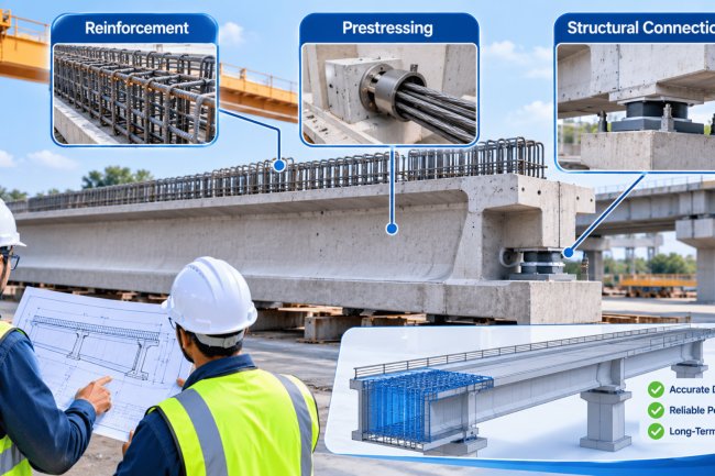
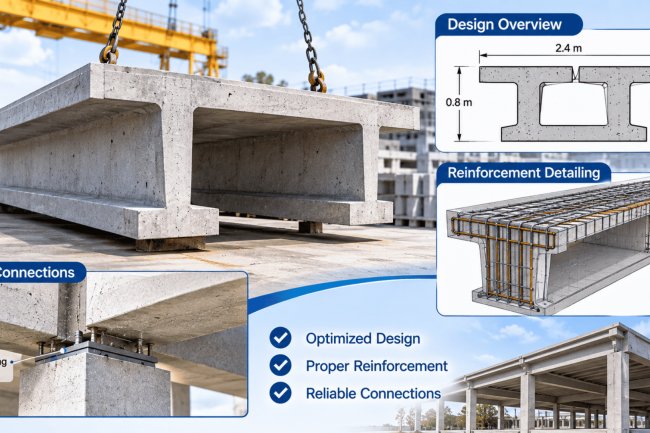
Precast Utility Structures: Detailing Manholes, Vaults & Underground Concrete Systems
A comprehensive technical reference for civil/structural engineers, precast detailers, and BIM professionals responsible for producing shop drawings, production drawings, and installation packages for precast underground utility infrastructure.

Types of Precast Underground Utility Structures
Precast concrete has become the dominant material choice for underground utility infrastructure due to its dimensional precision, factory-controlled quality, rapid field installation, and long service life under surcharge loading and corrosive soil environments. Each structure type carries distinct geometric, structural, and production detailing requirements.
Precast Manholes
Circular or rectangular precast manholes serve sewer, storm drain, water, and telecom networks. Standard products follow ASTM C478 (circular) or owner-specific rectangular configurations.
Components include base sections with integral inverts, riser barrels, eccentric or concentric cone reducers, flat-slab tops, and grade rings.
Inside diameters typically range from 48 in. to 144 in. for large interceptor manholes. Detailers must coordinate internal shelf elevations, pipe invert configurations, and step/rung spacing to OSHA requirements.
Electrical Vaults & Pull Boxes
Rectangular precast vaults house underground power distribution equipment, cable splices, switching gear, and fiber-optic terminations.
Configurations range from small pull boxes (24×36 in.) to large transformer vaults exceeding 12 ft × 20 ft in plan.
Roof slabs are designed for AASHTO HS-20 or HS-25 vehicular loading where located in traffic areas. Detailers must coordinate conduit entry knockouts, ground rod inserts, internal equipment pads, ventilation blockouts, and rated access frame and cover assemblies.
Utility Chambers & Junction Structures
Large precast utility chambers serve as junction points for multiple crossing utilities, storm sewer junction structures, wet wells, metering vaults, and valve chambers.
These structures commonly exceed 10 ft in internal height and require segmental construction with match-cast horizontal joints.
Structural detailing must account for lateral earth pressure, hydrostatic uplift, surcharge from overlying fill, and concentrated loads from internal mechanical and electrical equipment. Lifting and handling provisions are critical given unit weights frequently exceeding 50,000 lb.
Critical Structural Design Considerations
Key Detailing Requirements
Successful utility structure detailing requires far more than geometric drafting. Hydraulic requirements, utility coordination, loading conditions, constructability, transportation constraints, and long-term durability must all be integrated into a single fabrication-ready package.
Precast underground utility structures succeed because they combine factory precision with long-term structural performance. Whether detailing a manhole, electrical vault, or large utility chamber, the objective remains the same: deliver a durable, constructible, and serviceable infrastructure asset that performs reliably for decades underground.
Reinforcement detailing for precast utility structures must satisfy both the structural demands of soil, hydrostatic, and traffic loading and the production requirements of the precast plant. All details must reference ACI 318 for concrete design, ACI 350 for liquid-retaining structures where applicable, and the project-specific structural calculations. The following principles govern detailing across component types.
Structural Reinforcement Detailing: Walls, Base Slabs & Roof Slabs
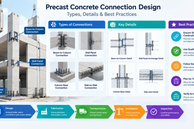
The connection details between a precast utility structure and the utilities it serves—and between individual precast segments—represent the most critical coordination points in the production drawing set. Errors in pipe penetration geometry, insert location, or joint configuration are among the most common and costly field problems in precast utility construction. The following details must be fully resolved before production drawings are released to the plant.
Fully detailed penetrations, blockouts, embedded inserts, and joint systems prevent the most common and costly field problems in precast utility construction.
Pipe Penetrations, Blockouts,
Embedded Inserts & Joint SystemsResolve connection geometry before the panel reaches the plant.
A complete precast utility structure detailing package must fully coordinate access systems, lifting requirements, rigging provisions, reinforcement detailing, and production documentation before fabrication begins. These drawing packages become the controlling documents for engineering review, plant production, quality assurance, transportation, and field installation, making accuracy and coordination essential to project success.
Access openings must provide safe maintenance access while maintaining structural integrity around the frame-bearing region. Opening geometry, reinforcement concentration, frame support zones, and grade-adjustment provisions require detailed coordination during the shop drawing phase.
Rigging systems must be engineered for production handling, storage operations, transportation staging, and final installation. Insert capacities, lifting configurations, pick geometry, and temporary handling forces should be evaluated as separate load conditions.
Precast structures often experience their highest stresses during lifting and handling rather than during service conditions. Temporary loading scenarios should be evaluated and reinforced where required to prevent cracking, distortion, or localized overstress.
Project data, structure identification, governing specifications, concrete design criteria, and reinforcement standards.
Full layout dimensions, penetration locations, inserts, embeds, and section references from established datums.
Complete bar schedules, splice requirements, reinforcement marks, bend shapes, quantities, and locations.
Material certifications, concrete quantities, insert schedules, quality-control records, and compliance documentation.
Pipe penetrations, seal systems, trim reinforcement, insert capacities, and embedment requirements.
Gasket systems, sealants, joint tolerances, waterproofing interfaces, and movement allowances.
Concrete quantities, reinforcement totals, hardware requirements, and procurement information.
Inspection references, testing requirements, QC checkpoints, and compliance verification records.
Production drawings represent the final fabrication authority for precast utility structures and must undergo rigorous engineering review before release. Complete coordination of access systems, reinforcement, lifting hardware, pipe penetrations, waterproofing details, and installation requirements is essential. Final drawing packages should carry the required professional engineering approvals, maintain revision control throughout the review cycle, and provide a complete technical record supporting fabrication, quality assurance, delivery, and successful field assembly.
Access Openings, Lifting Provisions & Production Drawing Requirements
Access Openings & Frame Bearing Zones
Lifting & Rigging Provisions
Temporary Handling Stress Checks
Production Drawing Requirements
Critical Drawing Components
Project Workflow
Professional Engineering Requirement
What's Your Reaction?