Double Tee Precast Concrete Detailing: Design, Reinforcement & Connections
Double tee (DT) precast concrete members are among the most widely used structural elements in modern construction — spanning parking structures, warehouses, office buildings, and institutional facilities across North America. Their distinctive two-stem cross-section delivers exceptional span-to-depth efficiency, making them the go-to solution for long-span floor and roof systems where speed of erection and structural performance are both critical priorities. Accurate precast double tee shop drawings and comprehensive detailing documentation are essential to ensure that these members perform as designed from casting through final installation. Every dimension, strand placement, embed location, and connection detail must be precisely coordinated between the structural engineer of record, the precast fabricator, and the erection contractor.
Geometry, Dimensions & Prestressing Strand Arrangements
Flange & Stem Geometry
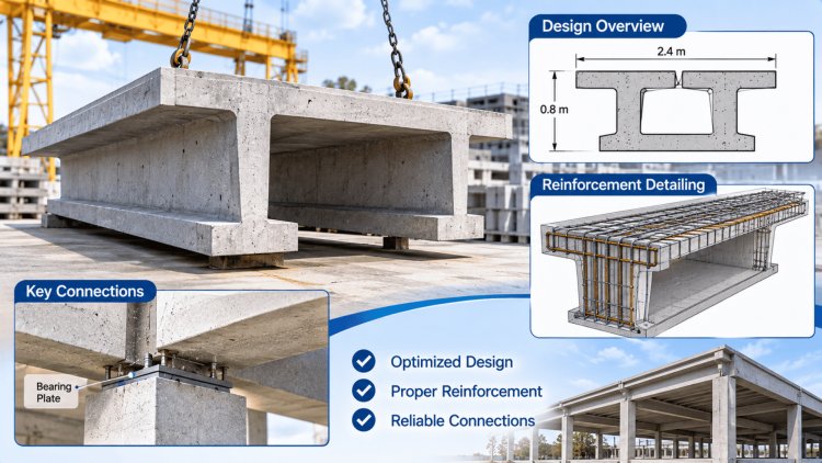
The double tee cross-section consists of a wide, relatively thin flange — typically 8 to 10 feet in width — supported by two vertical stems (webs) that extend downward to provide flexural depth. Standard flange thicknesses range from 2 inches for roof members to 3½ inches or more for floor systems subject to vehicular loading, as commonly required in parking structures.
Stem widths at the bottom typically taper from approximately 5–6 inches at mid-depth to 6–8 inches at the flange interface. Overall member depths range from 16 inches to 36 inches depending on span, loading, and camber requirements. Precast detailing standards per PCI Design Handbook govern all primary dimensional requirements.
Flange overhangs — the portion of the flange cantilevering beyond the outer stem — must be detailed with adequate transverse reinforcement to resist flexural tension under concentrated loads and thermal effects. Topping thicknesses, when specified, add composite depth and must be reflected in final section property calculations.
Prestressing Strand Arrangements
Prestressing strands are the primary longitudinal reinforcement in double tee stems. Low-relaxation 270-ksi, ½-inch or 0.6-inch diameter strands are most commonly specified. Strand patterns are carefully determined through iterative design to satisfy service-load stress limits, ultimate flexural strength requirements, and camber control at time of release and under long-term sustained loads.
Harped (draped) strand profiles are frequently employed to reduce end- zone tensile stresses and minimize the need for debonding. Debonded strands — where the bond is intentionally suppressed over a defined length at member ends — are an alternative approach used to control release stresses when harping is not feasible.
All debonded lengths and patterns must be clearly called out on the shop drawings.
Supplemental Reinforcement Requirements
Mild steel reinforcement is detailed in the flange to resist transverse bending, shrinkage, and temperature effects. Welded wire reinforcement (WWR) in the flange is standard practice.
Stem stirrups — typically closed or open U-bars — are provided for shear resistance and to satisfy minimum requirements per ACI 318 and PCI guidelines.
Max Standard Depth
Typical maximum stem depth for long-span double tee floor members in parking and warehouse structures.
Max Flange Width
Standard flange widths of 8 ft and 10 ft accommodate modular bay layouts and minimize field joints.
Strand Strength
Low-relaxation prestressing strand grade used in virtually all prestressed double tee design applications.
Achievable Spans
Double tees can achieve spans exceeding 80 feet under appropriate loading conditions with optimized strand layouts.
Successful double tee design depends on balancing section geometry, flange behavior, prestressing force, camber control, shear resistance, and constructability. Strand patterns, debonding layouts, and transverse reinforcement must work together to achieve both serviceability and ultimate strength requirements throughout the life of the structure.
Double tee performance is driven by the relationship between flange geometry, stem depth, prestressing strategy, and reinforcement detailing. When these variables are coordinated correctly, the result is an efficient long-span structural system with exceptional durability and constructability.
Proper bearing detail is fundamental to double tee structural performance. Inadequate bearing length, misaligned bearing pads, or improper seat geometry can lead to localized spalling, cracking at stem ends, and in extreme cases, structural instability. PCI and IBC provisions require minimum bearing lengths — typically 3 inches on concrete and 3½ inches on steel — with elastomeric bearing pads specified to distribute load uniformly and accommodate differential camber between adjacent members.
Elastomeric bearing pads beneath each stem must be sized to limit compressive stress within allowable limits. Hardness (durometer), plan dimensions, and thickness are all specified on the structural detailing drawings. PTFE or lubricated pads may be used where longitudinal movement is anticipated due to thermal expansion or creep. Pads must be centered on the bearing seat and shimmed level prior to member placement.
Raked or notched stem ends — common in architectural or exposed applications — reduce the net bearing area and must be carefully analyzed. The bearing seat itself, whether cast-in-place concrete corbel, structural steel ledger angle, or inverted-tee beam ledge, must be coordinated with the double tee detailing package for elevation, setback, and embed compatibility.
At the support, stem-end connections typically employ welded steel plates or angles cast into the double tee stem, field-welded to corresponding plates in the supporting member. These connections provide positive attachment, resist lateral forces, and accommodate erection tolerances. Weld sizes, electrode type, and inspection requirements must be explicitly noted on drawings.
Lateral ties and seismic connections — particularly in SDC C and above — require detailed engineering. Tie-back hardware cast into stems or flanges, combined with welded or bolted connections to supporting frames or shear walls, must be developed to satisfy diaphragm force demands. All hardware must be coordinated with the structural engineer's connection design and noted clearly on both the precast shop drawings and the structural drawings for the supporting system.
Minimum 3-inch bearing length on concrete seats; check for end-zone shear, bursting, and spalling. Provide confinement reinforcement at ledge reentrant corners per PCI requirements.
Minimum 3½-inch bearing on structural steel; specify steel hardness and ensure weld access for field connections. Coordinate with structural steel fabricator on embed and anchor bolt locations.
Cast-in hardware with field-welded connections for SDC C/D; engineer-of-record specifies force demands and hardware capacity. Deformation compatibility between DT and lateral system must be verified.
Bearing Conditions, Support Connections & Structural Interfaces
Bearing Pad Specifications
Stem-End & Lateral Connection Details
Concrete Bearing
Steel Ledger Bearing
Seismic Tie-Backs
Flange-to-flange connections, diaphragm detailing, and MEP opening coordination determine whether a double tee deck system can transfer lateral loads, maintain structural integrity, and accommodate building services without compromising the precast members.
Weld plates, grouted keyways, chord and collector embeds, blockouts, and hardware locations must be coordinated between the EOR and precast engineer.
Flange-to-Flange Connections,
Diaphragm Action & OpeningsDetail every flange connection, diaphragm embed, and opening before fabrication.
The most operationally critical phase of double tee precast construction is the development of complete fabrication drawings and coordinated erection documentation. These deliverables transform structural design into fabrication-ready and installation-ready instructions, ensuring every prestressing strand, embed plate, lifting insert, connection detail, and dimensional requirement is communicated clearly before casting begins.
A complete double tee shop drawing package must communicate all fabrication and installation requirements. These drawings serve as the primary production document used by precast plants, quality-control personnel, transportation teams, and erection crews.
Strand schedules must identify strand size, quantity, eccentricity, prestress force, and placement geometry. Accurate documentation is essential for maintaining consistency between engineering calculations and fabrication operations.
Predicted camber values at release, 28 days, and long-term service conditions should be included because differential camber directly affects floor elevation consistency, flange alignment, topping uniformity, and overall floor quality.
Shop drawings require formal review by the Engineer of Record before fabrication authorization. The review focuses on design conformity and compliance with structural intent, while fabrication accuracy and production methods remain the responsibility of the precast manufacturer.
Revisions must remain clouded and tracked through every review cycle until the final Approved-for-Construction release is issued.
Confirm bearing-seat elevations, support alignments, and installation tolerances before crane operations begin.
Utilize cast-in lifting hardware and spreader beams to maintain correct pick geometry while minimizing insert forces.
Complete welds and stem-end connections using planned sequences that limit thermal distortion and maintain alignment.
Perform grouting after bay completion to achieve continuous bonding and effective load transfer across adjacent tees.
Double tee members should be manufactured under PCI-certified quality systems with full traceability throughout production. Permanent project records typically include strand-placement verification, concrete batch tickets, compressive-strength testing, curing documentation, dimensional inspections, and camber measurements collected throughout fabrication.
Any field-approved modifications, installation adjustments, or approved deviations from Approved-for-Construction drawings must be documented through as-built markups and formally reviewed before project closeout.
Fabrication drawings are the operational backbone of every double tee project. Accurate shop drawings, disciplined review procedures, PCI-certified manufacturing controls, coordinated erection planning, and comprehensive record documentation work together to ensure structural performance, constructability, and long-term durability. The most successful precast projects treat detailing, fabrication, quality assurance, transportation, and installation as a single integrated process rather than isolated project phases.
Fabrication Drawings, Shop Drawing Standards & Installation Considerations
Shop Drawing Content Requirements
Strand Layout & Camber Documentation
Approval & Coordination Process
Erection & Installation Considerations
Survey Verification
Lifting Operations
Connection Installation
Keyway Grouting
Double Tee Delivery Workflow
Quality Assurance & Record Documentation
Final Professional Takeaway
What's Your Reaction?