Light Gauge Steel Seismic Design: Structural Detailing for Earthquake-Resistant Buildings
Cold-formed steel (CFS) framing has emerged as one of the most versatile and efficient structural systems for low- to mid-rise construction in seismic zones. As building codes grow increasingly stringent and earthquake hazard maps expand across North America, structural engineers and detailing professionals must master the nuances of light gauge steel seismic design — from load path continuity to shear panel configurations and code compliant anchorage. This presentation provides a rigorous, practice-focused overview of CFS seismic detailing principles, covering lateral load resisting systems, hold-down connections, strap bracing, and diaphragm behavior. Whether you are designing a multi-story residential structure in a high seismic zone or reviewing shop drawings for a mixed-use podium project, the guidance contained here addresses the most critical engineering decisions and common detailing pitfalls encountered in earthquake-prone regions.
Understanding Seismic Forces in CFS Structures
How Seismic Forces Act on CFS Framing
Earthquakes generate inertial forces that act horizontally on a building's mass. In cold-formed steel structures, these lateral forces must be collected at each floor diaphragm, transferred through shear walls, and finally dissipated into the foundation. Because CFS members are thin-walled and formed from sheet steel, their behavior under cyclic seismic loading differs substantially from hot-rolled structural steel.
Walls are slender, connections are discrete fastener-based, and global ductility depends heavily on system-level detailing rather than material plasticity alone.
Seismic Demand & Design Basis
The seismic demand on a CFS structure is quantified through ASCE 7 using the Seismic Design Category (SDC), spectral response accelerations (Ss and S1), and the response modification coefficient (R).
For CFS shear wall systems, AISI S400 provides the governing seismic design standard, defining system R values, overstrength factors (Ω₀), and deflection amplification factors (Cd) for strap-braced walls and sheathed shear walls alike.
Key Structural Characteristics of CFS Under Seismic Loading
Thin-Wall Buckling Susceptibility
Local and distortional buckling can occur in chord studs and tracks under combined gravity and seismic demands. Proper stud sizing and reinforcement are essential.
Connection-Governed Ductility
Unlike steel moment frames where ductility derives from member yielding, CFS seismic systems rely on fastener slip, bearing deformation, and controlled sheathing panel behavior to dissipate energy.
Lightweight Advantages and Challenges
Reduced mass lowers seismic base shear, but CFS's low dead load also increases overturning demands at shear wall end posts and hold-down connections.
System Redundancy
Multiple shear wall lines distributed in plan improve redundancy and reduce torsional irregularity — a critical consideration for SDC D and above.
Critical Code Requirement
AISI S400 Section E1 and E2 govern CFS seismic systems. Always verify that the R value used in ASCE 7 analysis matches the specific wall system detailed on the construction documents.
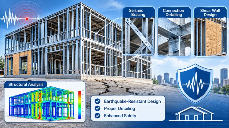
Successful seismic design in cold-formed steel structures depends less on individual member strength and more on complete system behavior. Shear walls, diaphragms, connections, hold-downs, and load paths must work together to provide ductility, energy dissipation, and reliable force transfer during an earthquake.
In CFS structures, seismic performance is achieved through coordinated system design. Properly detailed shear walls, ductile connections, controlled load paths, and code-compliant seismic detailing transform lightweight framing into a resilient lateral force-resisting system.
The two primary lateral load-resisting systems (LLRS) used in CFS seismic detailing are sheathed shear walls (wood structural panel or steel sheet) and strap-braced walls. Each system exhibits distinct stiffness, ductility, and detailing requirements that must be matched to the seismic demand, building height, and construction constraints of the project.
Structural sheathing panels — typically 7/16″ or 15/32″ OSB or plywood — are fastened to CFS stud framing with No. 8 or No. 10 screws at prescribed edge and field spacing. The wall's unit shear capacity, tabulated in AISI S400 Table E1.3-1, is a direct function of panel thickness, screw spacing, and stud thickness. Closer fastener spacing at panel edges increases capacity but requires careful layout to avoid splitting. Double-layer sheathing on both wall faces can double nominal capacity for high-demand walls.
Strap-braced walls (X-bracing or single-diagonal straps) work in tension only, with the strap designed to yield before connection failure — the ductile element in the system. AISI S400 Section E2 requires capacity-based design: connections, chord studs, and anchorage must be designed for the expected strap yield force (RyFyAg) multiplied by the overstrength factor. Strap width, thickness, and welded or screwed end connections must all be detailed to ensure the intended yield mechanism forms reliably under cyclic loading.
Panel aspect ratios are limited by code — AISI S400 restricts sheathed CFS shear walls to a maximum height-to-width ratio of 2:1 (or 4:1 with reduced capacity factors). In plan, shear walls must be distributed to minimize torsional eccentricity. Walls on a single line must be interconnected through rigid diaphragms so that load sharing is predictable. Where openings interrupt wall length, perforated shear wall methods per AISI S400 may be applied to account for the reduced net sheathed area while preserving structural continuity.
Lateral Load-Resisting Systems, Shear Walls & Strap Bracing
Sheathed Shear Walls
Strap Bracing Systems
Shear Panel Configuration & Load Distribution
A complete, uninterrupted seismic load path from roof to foundation is the single most important concept in earthquake-resistant CFS detailing. Hold-down anchors, foundation connections, diaphragm sheathing, collectors, and floor-to-wall connections must work together to transfer lateral forces safely to the foundation.
Coordinate hold-down anchors, foundation anchorage, diaphragm sheathing, collectors, and floor-to-wall connections to prevent progressive failure under seismic loading.
Hold-Down Anchors, Foundation
Connections & Diaphragm Load PathsMaintain a complete, uninterrupted load path from roof to foundation.
CFS seismic design is governed by an interlocking set of standards. ASCE 7 establishes seismic demands; AISI S400 (North American Standard for Seismic Design of Cold-Formed Steel Structural Systems) provides system-specific requirements; AISI S240 and AISI S230 address general framing and residential applications respectively; and the IBC integrates these into the building permit and inspection framework.
Engineers must navigate all four documents simultaneously, ensuring that system selection, detailing, and inspection requirements are aligned.
AISI S230 provides prescriptive tables for low-rise residential CFS construction in SDC A through D, reducing engineering burden for straightforward projects.
Engineered design per AISI S400 is required for SDC D and above in multi-story or irregular structures.
IBC Chapter 17 mandates special inspection for CFS seismic force- resisting systems, including verification of fastener type and spacing, hold-down installation, strap alignment, and anchor bolt placement.
The Statement of Special Inspections must clearly identify all CFS SFRS elements.
Non-structural components and cladding attached to CFS seismic systems must accommodate the system's design story drift (Cd × δe). Rigid finishes such as tile or stucco require flexible joints or isolation details to avoid damage during design-level ground motions.
Even experienced CFS detailing professionals encounter recurring challenges in seismic applications. Recognizing these pitfalls early — in design, not in the field — is essential for project success:
Cumulative gravity plus seismic axial demands often exceed single stud capacity at shear wall ends. Back-to-back or built-up stud posts with stitched connections at close spacing are frequently required at high-demand walls in multi-story CFS buildings.
Continuous rod tie-down systems accumulate elastic elongation over building height, increasing effective story drift. Engineers must include rod elongation in drift calculations to avoid exceeding ASCE 7 drift limits and triggering cladding or partition damage.
Plan irregularities — particularly re-entrant corners — concentrate diaphragm demands and require dedicated collector elements. These are frequently omitted in design or not clearly communicated on construction documents, leading to field improvisation and unverified connections.
Combining CFS shear walls with other lateral systems (e.g., wood shear walls at lower podium levels) introduces displacement compatibility issues. Relative stiffness must be carefully evaluated, and transition detailing between systems must be explicitly designed and shown on drawings.
Thorough peer review of CFS seismic details — particularly hold-down systems, collector connections, and chord stud designs — is strongly recommended for all SDC D and above projects before permit submission.
Successful seismic performance in cold-formed steel buildings depends on more than code compliance. Accurate load paths, robust hold-down systems, deformation compatibility, collector detailing, and rigorous inspection procedures must all work together to create a resilient seismic force-resisting system capable of performing under design-level earthquake demands.
Code Requirements, Engineering Challenges & Best Practices
Seismic Detailing Under Applicable Building Codes
Prescriptive vs. Engineered Design
Special Inspection
Deformation Compatibility
Common Engineering & Detailing Challenges
Chord Stud Overload
Rod Elongation & Drift
Incomplete Load Paths at Re-Entrant Corners
Mixed System Incompatibility
Recommended Best Practice
Key Takeaway
The most successful CFS seismic projects identify detailing risks during design, not construction. When code requirements, load paths, connection behavior, and deformation compatibility are coordinated from the outset, the entire structure performs as an integrated seismic system.
What's Your Reaction?