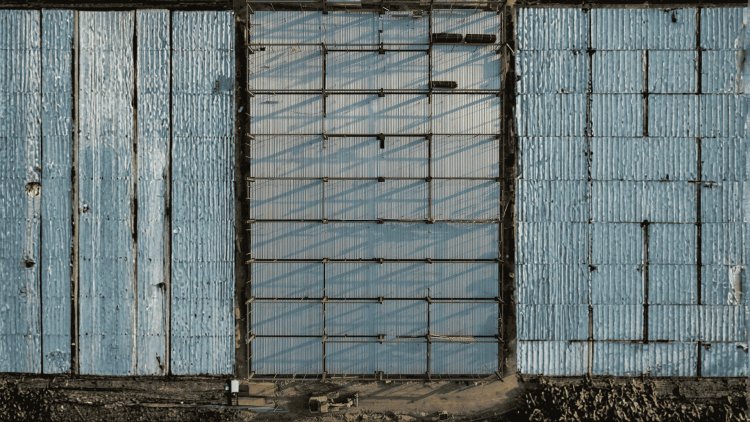
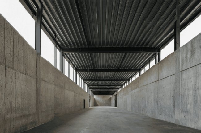
Steel Deck Fundamentals
Deck Direction & Structural Hierarchy
Load Path Defines the Structure
Deck
→
Joists
→
Beams
→
Columns
Deck ⟂ Joists
Most efficient layout. Deck spans across multiple joists, maximizing span capability and reducing framing demand.
Deck ∥ Beams
Requires additional secondary framing and often increases steel tonnage and connection complexity.
Where Problems Usually Appear
Re-Entrant Corners
Deck Direction Changes
Edge Conditions
Extra Framing
Deck Direction Is a System Decision
The orientation of the deck determines load paths, framing hierarchy, constructability, and coordination with MEP systems. Choosing deck direction early often has a greater impact on project efficiency than selecting the deck profile itself.
Efficiency Equation
Joist Spacing, Beam Spans, and Efficiency
The economic heart of deck direction decisions lies in how orientation interacts with joist spacing and beam span length. Each variable multiplies across hundreds of bays, so even modest per-bay improvements translate into significant project-wide savings in steel weight, fabrication hours, and erection time.
JOIST
Maximizing Joist Spacing
Standard 1.5″ Type B roof deck and 2″ composite floor deck have well-defined allowable span tables. Orienting deck so it spans in its strong direction allows joists to be pushed to maximum spacing — typically 5′–0″ to 6′–0″ for roof deck and 8′–0″ to 10′–0″ for composite floor deck under typical live loads.
- Wider joist spacing means fewer joists per bay.
- Reduces fabrication count, field connections, and bridging requirements.
- Fewer joists means fewer seats, fewer bearing details, and faster erection sequences.
BEAM
Beam Span Optimization
When deck direction is set early, girder and beam spans can be tuned to align with the most efficient structural steel sections. A 30′ bay with joists at 6′–0″ on center requires only four intermediate joist lines, each transferring a predictable tributary load to the girder.
- Flipping deck direction may require intermediate beams at 5′–0″ spacing to keep deck spans code-compliant.
- Across a 200,000 SF floor plate with 50 bays, that can mean 100 additional beam segments — a significant tonnage and cost adder.
- Long-span joists designed to match deck direction benefit from optimal depth-to-span ratios, keeping camber and deflection predictable.
SPAN
The efficiency equation is simple: set deck direction early, maximize joist spacing within allowable spans, and tune beam spans to match. This coordination minimizes steel tonnage, simplifies fabrication, and accelerates erection — turning a small per-bay decision into a major project-wide advantage.
Diaphragm Performance
How Orientation Affects Lateral Load Distribution
Deck direction directly impacts diaphragm shear capacity — the system’s ability to transfer lateral forces like wind and seismic loads to vertical resistance elements. Aligning deck orientation with demand is critical for both structural adequacy and economy.
Strong-Axis Diaphragm Shear
Highest shear values occur when lateral forces act perpendicular to deck flutes (parallel to span direction). Corrugated profiles resist in-plane shear efficiently, reducing fastener requirements. Aligning high-demand lateral direction with strong axis saves material and labor.
Weak-Axis Limitations
When demand is parallel to deck flutes, capacity drops. Remedies include increasing fastener density, reducing panel length, or adding supplemental strapping/collectors. These add cost and complexity. Orienting deck to align demand with strong axis avoids compensating measures.
Collector & Chord Design
Deck direction governs chord force accumulation. Perimeter beams or spandrels resist tension/compression from diaphragm bending. At irregularities or setbacks, chord continuity must be maintained with supplemental connections or drag struts to avoid conflicts.
Design Documentation
Explicit documentation of deck orientation and chord continuity is essential. Referencing SDI Diaphragm Design Manual tables during schematic design ensures diaphragm performance is considered alongside gravity framing efficiency.
Deck orientation is not just a framing efficiency choice — it is a structural performance decision. Aligning diaphragm strong axis with lateral demand reduces cost, improves adequacy, and simplifies detailing across the project lifecycle.
Deck Layout Strategy
Choosing the Right Deck Orientation
The Four Decision Gates
1. Bay Geometry
→
2. Framing Options
→
3. Diaphragm Demand
→
4. Constructability
Bay Geometry Rules
Rectangular Bays: Span deck in the short direction.
Square Bays: Compare both directions and diaphragm requirements.
Long Narrow Bays (>3:1): Short-direction spanning is usually most economical.
Irregular Plates: Maintain one dominant direction across most of the floor.
Load-Driven Exceptions
Heavy Equipment
Shear Stud Layout
Roof HVAC Loads
Cantilever Edges
Orientation Drives Efficiency
The best deck direction is usually the one that spans the shortest distance, aligns with the structural load path, and simplifies construction. Evaluate geometry, framing, diaphragm behavior, and constructability together before committing.
Key Takeaways
Efficient Framing Through Deck Direction
Deck direction is a high-leverage design variable that touches joist count, beam span economy, diaphragm performance, and constructability simultaneously. Treating it as a deliberate, calculated choice — rather than a drafting default — consistently produces leaner, more economical framing systems.
01
Set Deck Direction Before Sizing Members
Establish deck orientation during schematic design, before joist and beam sections are selected. Changing direction late can invalidate span tables, alter diaphragm calculations, and require re-detailing dozens of connections — at significant cost and schedule impact.
02
Maximize Allowable Deck Span First
Begin by checking the maximum allowable span for the selected deck profile and gage under the governing load combination. Designing to the full allowable span — rather than defaulting to conservative intermediate values — directly reduces intermediate framing requirements and is the single most effective lever for improving framing economy.
03
Align Deck Strong Axis with Primary Lateral Demand
Where site conditions and bay geometry permit, orient the deck so its strongest diaphragm direction aligns with the building's primary lateral demand axis. This minimizes required fastener density, reduces chord and collector design complexity, and avoids expensive compensating details at diaphragm boundaries.
04
Document Direction Changes Explicitly in Drawings
Every location where deck direction transitions — at re-entrant corners, setbacks, or stairwell edges — must be explicitly called out in structural drawings with supplemental details covering edge angles, lap conditions, and any required additional framing. Ambiguity at these transitions is a primary driver of RFIs, field delays, and cost overruns on metal deck projects.
DIRECTION
The engineers and detailers who treat deck direction as a primary design variable — not an afterthought — consistently achieve more efficient framing, fewer RFIs, and smoother construction. For deeper technical guidance on metal deck systems, joist detailing, and composite framing coordination, visit consac.com/blogs.