How to Present Deck Direction Clearly on Plans
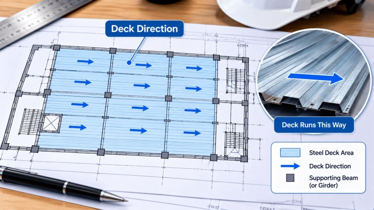
Deck orientation is one of the most consequential — and most frequently miscommunicated — pieces of information on a structural set. Whether you're detailing a composite floor system, a roof deck, or an open-web joist-supported deck, the direction in which the deck flutes run determines load path, diaphragm behavior, bearing requirements, and constructability. A single ambiguous note or missing arrow can send a fabricator in the wrong direction and cost days of rework in the field.
Why Deck Direction Matters — and Where It Goes Wrong
The Structural Stakes
Deck panels are orthotropic: their stiffness, strength, and load-distribution behavior differ dramatically between the strong axis (perpendicular to flutes) and the weak axis (parallel to flutes). Running deck in the wrong direction can violate the design span assumptions embedded in the deck tables the engineer of record used, reduce diaphragm capacity, and create bearing conditions the supporting members were never sized to handle.
Beyond structural performance, incorrect deck direction affects: pour-stop and edge-angle detailing, puddle weld and screw patterns, sidelap fastener layouts, and coordination with MEP penetrations that were designed around a specific flute orientation.
Where Miscommunication Originates
**Ambiguous or absent direction arrows:** Many plans show deck type and gauge but omit a clear flute-direction indicator, leaving the erector to guess.
**Conflicting notes vs. graphics:** A plan note says "deck spans north–south" while the section cut implies east–west bearing — a contradiction that only surfaces during shop drawing review.
**Assumed continuity across bays:** Deck direction changes at reentrant corners, elevator cores, and framing setbacks, but those transitions are rarely called out explicitly.
**Section/plan inconsistency:** The framing plan and the deck plan live on different sheets drawn at different scales, and direction arrows don't survive the copy-paste.
**RFI-driven changes not propagated:** A field RFI reverses deck direction in one bay; the EOR's sketch never makes it back into the issued-for-construction set.
The structural and steel deck industries have developed a set of widely accepted graphical conventions. Applying them consistently within a single set—and educating your team on what each symbol means—eliminates the majority of direction-related RFIs before they start.
Use zone-specific arrows, legible hatch patterns, explicit bearing callouts, and keyed deck schedules to prevent direction-related RFIs.
Standard Conventions for
Annotating Deck DirectionMake deck direction impossible to misread.
Uniform deck direction across an entire floor plate is the exception, not the rule. Cores, setbacks, cantilevers, and re-entrant corners all create zones where deck direction must change — and those transitions demand explicit, detailed documentation.
When deck from one bay runs perpendicular to deck from an adjacent bay, both deck systems bear on the same beam — from opposite sides and in perpendicular flute orientations. This “transition beam” must be:
At cantilever conditions, deck flutes must run parallel to the cantilever span to mobilize the deck's strong-axis bending capacity. This often conflicts with the deck direction in the adjacent back-span bay.
Document the transition clearly by showing:
Large floor openings (stairs, elevators, mechanical shafts) interrupt deck runs and create edge conditions on all four sides. Each edge requires a pour stop or closure strip, and the orientation of those accessories depends on whether the edge is parallel or perpendicular to the flutes.
Coordinate deck direction arrows with opening framing plans so the erector understands which edges are:
At re-entrant corners in an L-shaped or irregular floor plate, deck must turn the corner. This is never a smooth transition — the two perpendicular deck zones meet at a framing member that serves as a termination for both. The plan must show:
Any location where a direction arrow would need to “bend” to follow the floor plate is a location that needs an enlarged plan detail and a section cut. Never try to show a deck direction change using a single curved arrow.
Detailing Direction Changes, Transitions, and Special Conditions
Transition Beams and Double-Bearing Members
Cantilevers and Overhangs
Openings and Deck Terminations
Re-entrant Corners
Before a deck plan is issued for construction, run through this quality-control checklist. These checks are fast to perform and catch the vast majority of direction-related documentation errors before they become field problems or shop drawing rejections.
Confirm that each distinct deck zone — separated by framing conditions, direction changes, or deck type changes — contains at least one bold arrow labeled "DECK FLUTES RUN IN DIRECTION OF ARROW." Arrows should be sized to read clearly at the plotted scale. Do not rely on hatch patterns alone to communicate direction.
Pull up every section and detail that shows deck bearing on a support member. Confirm that the flute direction shown in section is consistent with the direction arrow on the plan. Cross-check at interior beams, edge beams, and walls. Inconsistencies between plan and section are among the most common — and most expensive — documentation errors in deck packages.
Search the plan for every location where deck direction changes. Confirm each transition has a labeled boundary, a transition beam note (if applicable), and an enlarged detail or section at minimum 3/4" = 1'-0". Double-bearing conditions are flagged for the structural engineer's review.
Verify that every deck zone label (D-1, D-2, etc.) appears in the deck schedule and that the schedule lists profile, gauge, coating, design span, design load, and a direction reference. The schedule should be on the same sheet as the deck plan wherever possible to minimize cross-sheet coordination effort for the reader.
After any revision that changes deck direction — even in a single bay — audit all related sheets: framing plan, deck plan, sections, details, and the deck schedule. Issue a revision cloud and delta on every sheet affected. Document the change in the revision block with enough specificity that a reviewer can understand what changed without comparing two full sets side by side.
Bottom line: Clear deck direction documentation is not a drafting nicety — it is a structural communication requirement. An explicit arrow, a consistent hatch, a cross-checked section, and a complete deck schedule cost minutes to produce and can save days of field rework. Build these practices into your standard QC process and enforce them at every issuance milestone. For more information please contact with us.
QC Checklist and Takeaways for Clear Deck Direction Documentation
Every Deck Zone Has an Explicit Direction Arrow
Plan Arrows Match Section-Cut Bearing Conditions
Transition Beams and Direction-Change Boundaries Are Called Out
Deck Schedule Is Complete and Linked to Zone Labels
RFI and Revision Changes Are Propagated to All Affected Sheets
What's Your Reaction?