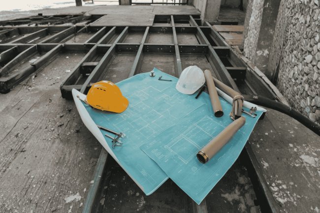
Deck Design Notes for Repetitive Building Bays
Metal deck installations in repetitive bay layouts present a unique set of engineering decisions that fall between the cracks of standard detailing guides. Whether you're coordinating composite floor decks across a parking structure, a warehouse, or a multi-story office building, the repeated geometry amplifies every decision — good or bad — across dozens or hundreds of identical bays. This presentation distills the practical design considerations, layout strategies, and coordination checkpoints that structural engineers, detailers, and BIM coordinators need to navigate these projects with precision and efficiency.
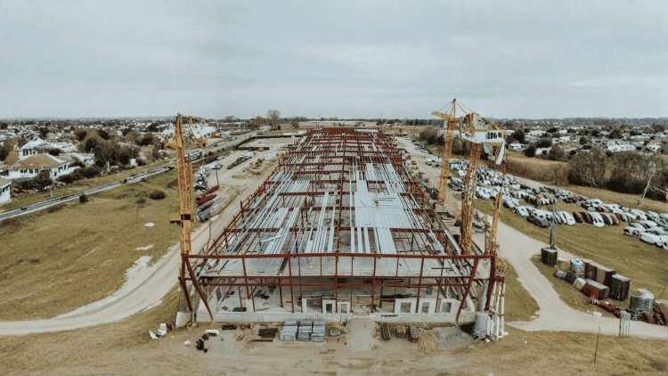
Why Repetitive Bays Demand a Different Workflow
Repetitive-bay projects amplify every detail decision. What affects one bay affects dozens or even hundreds of bays across the structure. Successful detailing therefore focuses on optimizing the bay system rather than individual isolated conditions.
The Compounding Effect
In a one-off framing condition, a minor detailing oversight might affect a single connection or a single pour stop. In a repetitive bay building, such as an 8×12 bay layout spread across a 200,000 sq ft floor plate, that same oversight is multiplied across every identical bay.
A misplaced button-punch pattern, an inconsistent bearing condition at a support angle, or a deck orientation that conflicts with framing direction can generate hundreds of RFIs, installation confusion, and significant field rework.
The economics of repetition work both ways: efficiency when right, costly when wrong.
These decisions form one system. Resolve flute direction, support span, profile, gauge, MEP coordination, and construction loading together—not as separate sequential choices.
For typical composite framing, deck ribs are generally oriented perpendicular to the primary supporting beams or joists so the deck spans efficiently and composite stud placement can be coordinated. The exact design must follow the governing code, deck system, and structural model. [29][32]
In repetitive bays, select one profile and gauge that satisfies the governing typical-bay condition, then use it consistently rather than creating many bay-by-bay transitions.
Reserve gauge changes for clearly atypical transfer bays, heavy point loads, long spans, or materially different live-load criteria.
A 3-in. composite profile is widely used for longer repetitive floor spans; manufacturer literature commonly places many 3-in. products in roughly the 10–14 ft optimal range, while exact capacity depends on profile, gauge, loading, and support condition. [14][41]
The deck must be checked for wet concrete, construction live load, equipment, and the actual pour sequence. SDI guidance notes that allowable span information commonly includes deck and concrete dead load plus construction loading such as 20 psf or a specified point load. [37]
The best deck specification is not the thinnest gauge or the deepest profile considered separately. It is the coordinated combination of orientation, span, profile, gauge, MEP compatibility, and temporary-load performance that can be detailed and installed consistently across the building.
Deck Orientation, Span Direction & Gauge Selection
Orient the Flutes
Optimize Span and Gauge Together
Choose the Profile with MEP in Mind
Verify Temporary Loading
Schematic Detailing Sequence
The Integrated Selection Principle
In repetitive deck bays, small detailing oversights can compromise diaphragm performance, bearing adequacy, and perimeter closure. These checkpoints ensure structural assumptions are valid in the field.
Sidelap spacing controls diaphragm shear capacity. Uniform schedules (e.g., 36" button punch) may not suffice near stair cores or shear wall collectors. Increased fastening must be explicitly detailed on placement plans.
SDI requires minimum 1.5" bearing. Tight flange widths on secondary beams can complicate weld access. Sequencing notes may be needed, especially at cantilevered conditions where end bearing transfers negative moment.
Pour stops must resist hydrostatic pressure of wet concrete and be anchored consistently. Anchor spacing must be verified against slab thickness and deck height. Corner bays, re-entrant corners, and mechanical curbs require individual review.
Welds or fasteners at deck-to-joist interfaces transfer diaphragm collector forces. A single "36/4 weld pattern" may not suffice. Perimeter and collector lines often require welds at every flute, increasing labor and requiring explicit coordination.
Critical checkpoints — sidelap fastening, end bearing, pour stops, and weld patterns — must be verified bay by bay. Uniform notes are insufficient; explicit detailing ensures diaphragm integrity and constructability in the field.
Critical Detailing Across the Typical Bay
1. Sidelap Fastening Pattern
2. End Bearing at Steel Supports
3. Closure & Pour Stop Details
4. Deck-to-Joist Weld Pattern
Key Insight
A repetitive-bay building should not simply be documented as repetitive. The repetition itself should become a coordination asset inside the BIM environment. When modeled correctly, repetitive bay systems accelerate reviews, reduce conflicts, simplify change management, and dramatically improve fabrication and installation accuracy.
BIM Coordination Strategies for Repetitive Bay Decks
Use Repetition as a Coordination Tool
Typical Bay Type
• Repeated geometry
• Standard deck orientation
• Consistent fastening patterns
• Centralized change managementAtypical Bay Type
• Long-span framing
• Equipment support zones
• Core interruptions
• Unique detailing requirements
Repetitive bay buildings reward disciplined upfront coordination and punish ad hoc detailing. These principles, applied consistently from schematic design through shop drawing approval, define the difference between smooth deck installation and costly RFIs or rework.
Design and detail the typical bay as the primary unit of work. Perimeter, atypical, and transition conditions must be explicitly called out rather than assumed to follow the typical.
Deck flute orientation, span direction, and joist framing must be coordinated before detailing. Orientation change lines are mandatory on placement plans and must align with pour stop and closure details.
Use a single gauge sized to the worst-case condition. Reserve gauge transitions for atypical bays only. Document exceptions in BIM models and structural drawings with specific callouts.
Field welds, sidelap fasteners, and collector welds must be shown as distinct zones on placement plans. Perimeter and collector bays often require denser weld patterns than interior bays.
Fix bay grid and deck orientation early.
Create a coordinated typical bay detail set.
Identify and document all nonstandard bays.
Align model geometry with placement plans.
These phases are not strictly sequential — orientation and atypical bay identification often happen in parallel. But each must be explicitly completed and documented before shop drawing submission. Skipping or compressing any phase is the most common source of costly mid-project corrections.
Key Takeaways for Repetitive Bay Deck Design
Treat the Bay as the Unit
Resolve Orientation Early
Uniform Gauge, Explicit Exceptions
Differentiate Weld Zones
Lock Grid & Orientation
Develop Typical Details
Detail Atypical Bays
Coordinate BIM & Placement
Key Insight
What's Your Reaction?