Floor Deck Detailing for Office Building Projects
Precision detailing of composite floor decks is one of the most consequential—and often underestimated—disciplines in structural steel documentation. For office building projects, where floor-to-floor heights, point loads from mechanical equipment, and long-span framing schemes intersect with tight construction schedules, the quality of deck details directly affects constructability, structural performance, and downstream trade coordination. This presentation breaks down the critical detailing decisions that structural engineers, floor framing detailers, and BIM modelers face on every typical office project—from slab thickness and bearing requirements to pour stop conditions, sidelap fastening, and edge-of-slab callouts.
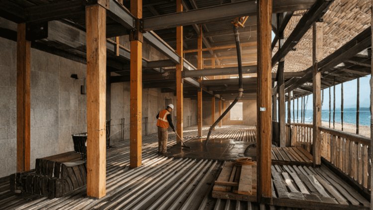
Why Floor Deck Detailing Demands Special Attention on Office Projects
Office buildings may appear structurally straightforward compared with industrial facilities or complex manufacturing plants, but floor deck detailing on office projects carries uniquely demanding requirements. Long-span composite framing, vibration-sensitive occupancies, dense MEP infrastructure, phased construction schedules, and architecturally exposed building envelopes all place extraordinary pressure on the deck detailing process. Small detailing oversights frequently result in field conflicts, schedule delays, expensive remediation, and unnecessary redesign.
The Stakes Are Higher Than They Appear
Office buildings demand a balance of structural efficiency, architectural flexibility, occupant comfort, and construction speed. Floor deck detailing sits at the center of all four objectives.
Why Office Floor Systems Are Different
Small Errors Create Large Problems
Undersized deck bearing, omitted closure angles, incorrect deck gauge selections, missing reinforcement details, and miscoordinated stud layouts may appear minor during detailing but often become expensive field corrections involving steel modifications, deck replacement, concrete delays, and engineering review.
Long-Span Composite Framing
Modern office buildings frequently utilize large column spacing and expansive floor plates to maximize leasing flexibility. Spans of 30 to 40 feet are common, placing greater importance on deck orientation, beam camber, composite stud spacing, and concrete slab performance.
Vibration Criteria Often Govern Design
Unlike industrial structures where strength controls many design decisions, office floors are frequently governed by vibration and serviceability requirements. The combination of slab thickness, deck profile selection, concrete weight, and composite action influences how occupants perceive floor movement.
Mechanical & Electrical Penetrations
Office towers contain extensive HVAC systems, electrical distribution networks, communications infrastructure, plumbing systems, and life-safety components. As a result, floor deck layouts must anticipate numerous openings requiring framing, reinforcement, and coordinated installation procedures.
Phased Construction Magnifies Detailing Errors
Office projects often move rapidly from steel erection to deck placement. In many cases, deck installation begins while other design decisions are still evolving. This leaves little opportunity to resolve major detailing conflicts after fabrication has started, making early accuracy essential.
Curtain Wall Interfaces
Modern office buildings rely heavily on curtain wall systems and architecturally exposed perimeter treatments. Edge-of-slab conditions must be carefully coordinated with façade anchors, embeds, pour stops, closure angles, insulation systems, and fire-stopping requirements.
Edge-Of-Slab Coordination Requirements
Selecting the appropriate composite deck profile and establishing its direction relative to the supporting framing are foundational detailing decisions. The choice affects span capability, slab depth, construction performance, shear-stud coordination, and the final composite design.
Deck orientation should be clearly identified on the layout and verified against the structural engineer's composite design assumptions.
Run deck perpendicular to supporting beams to establish the intended composite action and coordinate headed shear studs with the deck ribs.
Where deck runs parallel to a supporting beam, such as at an edge or irregular framing bay, the detail should explicitly identify the non-composite condition or provide the required supplemental framing solution.
Confirm that the deck direction shown in the BIM model matches the structural design assumptions. Reversing a deck bay can affect composite calculations, bearing conditions, and shear-stud placement at the same time.
The correct deck profile is only half the decision. The selected profile must be paired with the correct span direction and verified against the structural model, beam framing, and shear-stud layout. Resolving these decisions before shop drawings are released prevents one orientation error from propagating through the entire composite floor system.
Deck Profile Selection and Orientation: Getting the Foundation Right
Deck Orientation Callouts
Structural drawings must distinguish total slab thickness from concrete above the flute. For example, a 3.5″ LW slab on 2″ deck yields only 1.5″ above flute — critical for fire rating and composite properties. Office projects typically specify 3.25″–4.5″ depending on span, load, and vibration. Confirm thickness against DMA tables and composite calculations, and explicitly call out LWC vs. NWC as unit weight impacts camber, deflection, and stud capacity.
SDI standards require a minimum 1.5″ bearing on steel framing. While interior beams usually comply, spandrel beams, transfer beams, and re-entrant corners demand verification. Reduced bearing below 1.5″ requires supplemental closure plates or additional weld specifications to maintain structural integrity.
Fastening governs diaphragm capacity and must follow the engineer’s design. Two systems are common:
Large office floor plates often have shifting diaphragm zones. Detailers must coordinate fastening boundaries with the engineer to ensure correct patterns are applied regionally, not blanket across the floor.
Slab thickness, bearing, and fastening are non-negotiable parameters. Proper verification and coordination ensure compliance with SDI standards, structural safety, and long-term performance of composite floor systems.
Slab Thickness, Bearing & Fastening: The Three Non-Negotiables
Slab Thickness Above the Deck
Deck Bearing on Steel Supports
Sidelap and Support Fastening
Key Insight
Edge-of-slab conditions are among the most detail-intensive areas of any office building floor system. These locations require careful coordination between floor deck detailing, structural steel framing, concrete containment systems, curtain wall anchors, and architectural envelope requirements. Because multiple trades converge at the slab perimeter, incomplete deck details frequently result in field conflicts, costly rework, and construction delays.
Office buildings with curtain wall systems leave little room for interpretation. Pour stops, closure angles, embeds, anchors, deck terminations, and reinforcement details must all be coordinated directly within the deck drawings.
A continuous closure form or pour stop retains wet concrete at the slab perimeter during placement. These components are structural construction elements that must be capable of resisting wet concrete pressure until the slab hardens. The deck detail should clearly define size, gauge, fastening requirements, and installation limits.
Open flute ends create clear pathways for concrete flow during placement. Closure angles seal the deck profile at slab edges, supporting proper concrete containment and maintaining a clean slab termination condition.
Closure angles located near spandrel beams must be coordinated with anchor rods, embed plates, façade anchors, and curtain wall attachment hardware. Failure to show exact placement frequently creates installation conflicts during construction.
Modern office buildings frequently use the concrete slab edge as the primary support point for curtain wall systems. Proper detailing requires complete coordination between structural framing, concrete slab geometry, façade support systems, and deck accessories.
Floor setbacks, tower offsets, mechanical penthouse floors, and stepped building geometries introduce conditions where standard edge details no longer apply. Each re-entrant corner requires project-specific detailing for deck termination, concrete containment, and reinforcement continuity.
Edge-of-slab conditions represent one of the most coordination-sensitive portions of an office building structure. Pour stops, closure angles, deck terminations, curtain wall anchors, embed plates, and slab reinforcement all converge within a narrow zone that directly impacts both structural performance and building envelope installation. Comprehensive detailing, backed by close coordination between the structural engineer, curtain wall consultant, and deck detailer, is essential to eliminate field conflicts and ensure successful construction of the slab perimeter.
Edge Conditions, Pour Stops, and Closure Angles
The Slab Edge Must Be Fully Resolved Before Construction
Why Slab Edge Conditions Generate Conflicts
Standard Pour Stop (Closure Form)
Closure Angles At Flute Ends
Spandrel Beam Conflict Zones
Slab Edge At Curtain Wall Systems
Information The Deck Detail Must Show
Slab Geometry
Façade Supports
Concrete Containment
Structural Reinforcement
Required Design Coordination
Re-Entrant Corners & Building Setbacks
Common Challenges At Re-Entrant Corners
Re-Entrant Corner Detailing Process
Edge Details Cannot Be Left To The Field
Modern office projects depend on coordinated BIM models, and floor deck detailing must be treated as more than visual geometry. The model should carry the information required for coordination, quantity takeoff, shop drawings, clash detection, and field installation.
Verify the selected profile and gauge against the applicable design tables, manufacturer information, and composite design calculations before fabrication release.
Review every deck bay individually. Flag parallel-to-beam conditions and explicitly resolve whether each condition remains composite or requires a non-composite or supplemental-framing solution.
Check standard and non-standard support conditions, including spandrel beams, transfer framing, narrow flanges, and any locations where available bearing may be reduced.
Coordinate slab-edge conditions with curtain wall drawings, embeds, setbacks, and architectural elevations before concrete placement begins.
Provide clearly dimensioned fastening-zone boundaries on the floor framing plan and distribute the coordinated requirements to the deck installer.
The strongest office deck models leave little or nothing to field interpretation. Profile, gauge, orientation, bearing, closures, fastening zones, and slab-edge conditions should be coordinated as structured model information and then carried consistently into the shop drawing package.
BIM Modeling Best Practices & Coordination Checklist
Coordination Checklist
Confirm Deck Profile and Gauge with the Structural EOR
Check Deck Orientation in Every Bay
Verify Bearing Lengths at All Supports
Coordinate Pour Stops and Closure Angles
Issue the Diaphragm Fastening Zone Plan
What's Your Reaction?