Precast Concrete Staircase Detailing: Landings, Flights & Reinforcement Layouts
A comprehensive technical reference for structural engineers, precast detailers, and fabrication shop managers covering staircase configurations, dimensional standards, reinforcement layouts, connection design, and the preparation of compliant shop drawings for precast stair systems.
Precast Staircase Configurations & Dimensional Standards
Selecting the correct staircase configuration is the first critical decision in precast detailing. Each system imposes unique structural demands, bearing conditions, and fabrication constraints. Understanding dimensional standards ensures code compliance and seamless integration with the structural frame.
Straight-Flight Stairs
The simplest and most economical precast configuration. A single inclined slab spans between two bearing points — typically a landing beam or structural wall at the top and a floor slab or pad at the bottom.
Standard waist slab thickness ranges from 150 mm to 250 mm depending on span, and tread widths typically run 250–300 mm with risers of 150–180 mm.
Minimal forming complexity makes this the preferred choice for parking structures and industrial facilities.
L-Shaped Stair Systems
Combines one straight flight with an intermediate landing, changing direction by 90°. The landing unit is typically a separate precast element with corbels or embedded bearing plates that receive the flight.
This configuration suits mid-rise residential and commercial structures where core geometry is constrained.
Detailers must carefully coordinate landing cantilever lengths, bearing widths (minimum 75 mm for precast-on-precast), and the differential shrinkage behavior between the landing slab and flight slab.
U-Shaped (Half-Turn) Systems
Comprises two parallel flights connected by a 180° landing, occupying a compact rectangular core. U-shaped systems are common in high-rise residential towers.
The intermediate landing must be engineered to transfer loads from both flights simultaneously. Precast landing units are often cast monolithically with one flight to reduce field connections and improve structural continuity.
Clear landing width must accommodate handrail anchorage zones and satisfy applicable building codes (IBC minimum 36 in. / 915 mm).
Key Dimensional Parameters
Regardless of configuration, the following dimensional standards govern precast stair detailing:
Landing Geometry & Tolerance Considerations
Landing slabs must be sized to provide adequate bearing for incoming flights on both sides while accommodating architectural finishes. Critical detailing parameters include:
Successful precast stair detailing begins with selecting the appropriate configuration and accurately coordinating dimensions, bearing conditions, tolerances, and landing geometry. These decisions drive fabrication accuracy, erection efficiency, code compliance, and long-term structural performance.
Every precast staircase is a balance of geometry, structural behavior, constructability, and code compliance. When flight dimensions, landings, bearings, and tolerances are coordinated correctly, installation becomes predictable and long-term performance is assured.
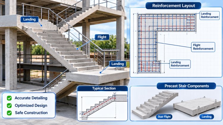
Reinforcement detailing for precast stairs must address flexural demand along the inclined waist slab, local punching and torsional effects at landing corners, development length requirements at bearing ends, and the special demands imposed during stripping, transport, and erection. The bar bending schedule (BBS) translates structural drawings into fabrication-ready data, and its accuracy directly impacts plant productivity and structural performance.
The primary flexural steel runs parallel to the flight pitch along the bottom face of the waist slab. Bar sizes typically range from #4 to #7 (12–22 mm), spaced at 150–200 mm on center. Bars must be fully developed beyond the bearing edge — development length per ACI 318-19 Section 25.5 — using standard 90° hooks where clear distances are limited. At the top of the flight, bars may be bent into the landing to provide continuity and reduce cracking at the re-entrant corner, one of the most stress-concentrated regions in a stair assembly.
Transverse bars control crack widths perpendicular to the span direction and distribute concentrated loads from individual treads. Minimum transverse steel is typically 20–25% of the longitudinal area, placed at the top face. In wide stair units (>1,200 mm), transverse steel demands increase due to torsion from eccentric loading. Detailers should specify transverse bars at both top and bottom mats in this case, with closed stirrups or ties at the flight edges providing confinement.
The junction between tread and riser is a flexural discontinuity point susceptible to cracking under service loads and during demolding. Small diagonal bars (#3 or #4 at 300 mm o.c.) placed at 45° across the inside corner of each tread-riser junction are standard practice in quality precast plants. Some specifications call for fibre-reinforced concrete (FRC) in the tread zone as a supplementary crack control measure, particularly for exposed architectural stairs.
Landing slabs behave as two-way plates when supported on three or four sides. Reinforcement is therefore required in both directions at top and bottom faces. At re-entrant corners where the landing meets a wall or flight, diagonal corner bars (typically 2 × #5 at 45°) prevent crack propagation under sustained and live load. Where the landing cantilevers from a wall, top steel governs and must be designed for the full cantilever moment including dynamic loading from foot traffic.
A compliant BBS for precast stair units must include: bar mark, bar size/diameter, number of bars per unit, total number of bars, cutting length, bending shape code (per ASTM A615 or BS 8666 as applicable), bend dimensions A through E, unit weight, and total steel weight. The BBS is cross-referenced to plan, elevation, and section views. Errors in development lengths or hook dimensions are among the most common — and costly — fabrication shop corrections. BBS should always be reviewed against the structural engineer's design calculations before release for fabrication.
Cage Fabrication
Bar Bending Schedule
Reinforcement Layout
Structural Design
Reinforcement Layouts & Bar Bending Schedules
Longitudinal Bottom Steel — Flight Slab
Transverse Distribution Steel
Tread & Riser Corner Reinforcement
Landing Reinforcement & Two-Way Action
Bar Bending Schedule (BBS) Requirements
Connection design is the most structurally critical and coordination-intensive aspect of precast stair detailing. Connections must transfer gravity loads, resist lateral forces (particularly in seismic zones), accommodate thermal and creep movement, and facilitate safe erection without temporary propping wherever possible. Each interface—stair-to-wall, stair-to-landing, and stair-to-floor—has distinct detailing requirements.
Select the connection type for gravity, lateral, seismic, and erection demands—and document every bearing, embed, weld, and lifting provision on the shop and erection drawings.
Connections: Stair-to-Wall,
Stair-to-Floor & Bearing DetailsDetail the bearing, restraint, and lifting path before fabrication.
The final deliverable in precast stair detailing is a fully coordinated drawing package that allows fabrication teams to produce units accurately and installation crews to erect them safely. Drawing quality directly influences fabrication efficiency, construction sequencing, dimensional accuracy, quality assurance, and project schedule performance.
Fabrication documentation must fully define geometry, reinforcement, connection systems, lifting requirements, and installation conditions. Every detail required for manufacturing, transportation, erection, and inspection should be clearly documented before production begins.
Handling drawings must clearly identify lifting insert locations, rigging geometry, load capacities, and center-of-gravity positions. These details are essential to prevent damage during stripping, transportation, storage, and installation.
Erection notes should define cure-strength requirements, temporary bracing requirements, alignment tolerances, and installation sequence recommendations to ensure safe field operations.
Each precast stair unit should be assigned a unique identifying mark linked to fabrication records, casting dates, concrete testing results, finish specifications, and delivery documentation.
Proper identification simplifies quality assurance, supports inspection activities, and creates long-term project traceability throughout the structure's lifecycle.
A precast stair drawing package serves as the single source of truth for fabrication, transportation, installation, inspection, and quality assurance. Thorough coordination, comprehensive reinforcement detailing, accurate dimensional control, and formal engineering review dramatically reduce field conflicts, minimize RFIs, improve production efficiency, and ensure that finished stair units perform exactly as intended. Successful projects treat drawing preparation not as drafting work, but as a critical engineering process that drives every downstream stage of construction.
Fabrication & Installation Drawing Preparation
Complete Drawing Package Requirements
Lifting & Handling Documentation
Finish & Traceability Information
Coordination Checklist Before Drawing Release
Drawing Development Workflow
Final Professional Takeaway
What's Your Reaction?