Insulated Precast Concrete Sandwich Panels
Layer Design, Connectors & Thermal Performance — a technical reference for precast engineers, architects, and designers working with high-performance insulated wall systems.
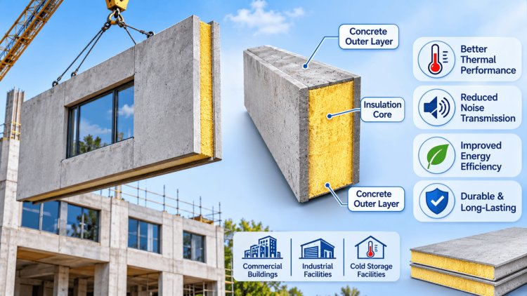
Anatomy of a Sandwich Panel: Layer Construction
A precast concrete sandwich panel consists of three primary layers working in composite or non-composite action. Understanding the role and coordination of each layer is fundamental to achieving structural integrity and thermal efficiency.
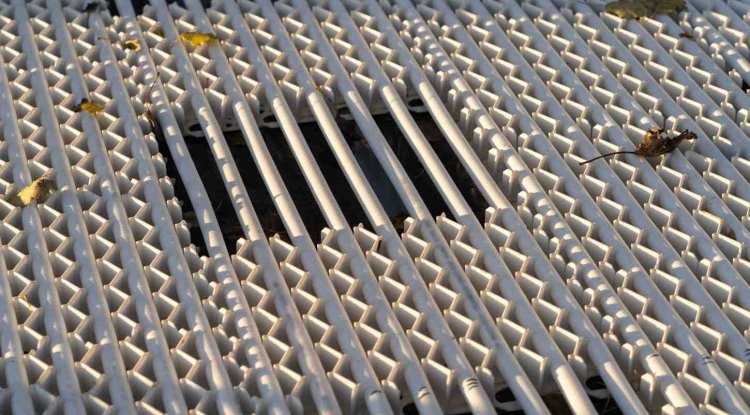
Wythe connectors span the insulation layer, mechanically linking the inner and outer concrete wythes. Their selection and placement directly determine the panel’s composite action level, thermal performance, and long-term durability.
Non-composite designs allow free differential movement between wythes, reducing restraint stresses while improving thermal continuity.
Wythe Connectors &
Structural Load TransferAllow differential movement while preserving thermal continuity.
Achieving code-compliant thermal performance requires minimizing heat flow pathways through the panel assembly while managing moisture risk at critical interfaces.
Both wythes require independent reinforcement designed for their respective load conditions:
Reinforcement detailing must be coordinated with both insulation geometry and hardware placement.
Thermal Bridging, Moisture Management & Reinforcement
structural steel or strand
continuous to edges
temperature / shrinkage steelReinforcement Arrangements
Thermal & Moisture Detailing
Successful sandwich panel projects are won during detailing, not after fabrication. Structural performance, thermal efficiency, architectural quality, and installation success depend on coordinated shop drawings that fully resolve reinforcement, insulation, connectors, hardware, lifting systems, tolerances, and erection requirements before concrete placement begins.
Fabrication begins with accurate form setup and layout verification. Hardware locations, embed coordinates, connector grids, lifting devices, and architectural finish requirements must be established before reinforcement and insulation placement begins.
Reinforcement, thermal connectors, embeds, lifting inserts, and connection hardware must be coordinated carefully to avoid conflicts. Proper positioning is essential for both structural load transfer and long-term panel performance.
The insulation layer must fit tightly around connectors, embeds, and blockouts while maintaining continuous thermal performance. Proper sequencing and inspection before closing the form are critical to eliminating thermal bridges.
Following stripping, dimensional verification, connector inspections, finish reviews, and tolerance checks confirm conformance with project requirements and PCI quality standards.
Sandwich panels are commonly fabricated with the architectural wythe placed face-down first, followed by insulation installation and finally the structural wythe. This sequence directly influences connector installation, lifting insert orientation, embedded hardware positioning, and final erection geometry.
Shop drawings should clearly identify casting orientation and hardware placement requirements to avoid fabrication errors that become difficult and expensive to correct after curing.
Insulation boards should be accurately cut around connectors, embedded items, lifting devices, and blockouts without creating voids or discontinuities. Multiple insulation layers should utilize staggered joints whenever possible to reduce thermal pathways through the assembly.
Installation drawings must define bearing locations, temporary bracing points, rigging arrangements, support conditions, and final structural connections. Tolerance stacking between panels and adjacent structural systems should be reviewed before fabrication approval.
Verify reinforcement placement, connector locations, cover requirements, and hardware positioning.
Confirm insulation continuity, board fitment, joint alignment, and connector penetration integrity.
Compare finished dimensions against design requirements and PCI MNL-135 tolerance criteria.
High-performing sandwich panel projects succeed because structural, thermal, architectural, and erection requirements are coordinated before concrete is placed. The most effective detailing packages integrate casting logic, insulation continuity, hardware placement, connection design, quality control checkpoints, and installation sequencing into a single fabrication-ready workflow. When coordination is completed upfront, fabrication becomes predictable, installation proceeds smoothly, and long-term panel performance meets both structural and energy-efficiency objectives.
Detailing for Fabrication & Installation
Form Preparation
Steel & Hardware
Casting & Insulation
Stripping & QC
Layer Sequencing in the Form
Insulation Coordination
Erection & Connection Detailing
Quality Control Milestones
Final Engineering Takeaway
What's Your Reaction?