Precast Concrete Column and Beam Detailing: Structural Connections & Shop Drawings
Precast concrete column and beam systems represent one of the most structurally demanding disciplines in the precast industry. Unlike cast-in-place concrete, precast components must be fully detailed, reinforced, and connection-ready before they ever leave the plant — leaving no room for field improvisation at critical load-transfer points. For structural engineers, precast detailers, and fabrication managers, achieving precision in precast beam column detailing is not just a quality standard; it is a fundamental safety and constructability requirement.
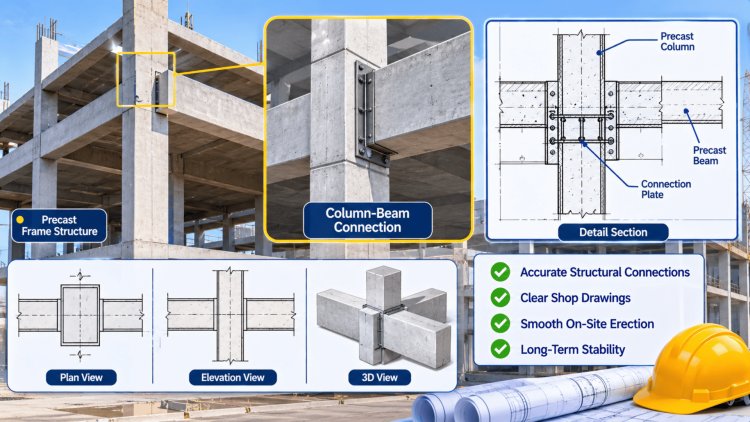
Understanding Precast Beam-Column Structural Systems
System Overview
Precast beam-column frames function as gravity and lateral load-resisting systems where individual components — columns, beams, and their connections — must work in concert to distribute forces safely. Unlike monolithic concrete, precast systems rely on designed connection interfaces rather than continuous concrete mass, making connection detailing the most critical phase of structural design.
Columns typically run one to three stories in height and are connected at base plates, mid-height splices, or column caps. Beams span between column corbels or embed pockets, bearing on elastomeric pads or steel bearing plates.
The load path from beam to column must be clearly defined in both the structural design and the shop drawing package.
Structural Frame Types
Gravity Frames
Beams bear on corbels; lateral resistance provided by shear walls or braced cores.
Moment-Resisting Frames
Beams are moment-connected to columns via embedded plates and field-welded connections.
Hybrid Systems
Precast columns combined with cast-in-place diaphragms or topping slabs to achieve composite structural behavior.
Multi-Story Stacked Columns
Columns stacked vertically with grouted sleeve or mechanical splices at each story level.
Why Connection Design Matters
In precast construction, structural performance depends on the continuity provided by connections rather than continuous concrete. Corbels, embed plates, bearing assemblies, splice locations, grout pockets, welded assemblies, and diaphragm connections must all be coordinated to ensure gravity, shear, moment, uplift, and seismic forces follow a clearly defined load path through the structure.
Understanding which frame system is in use determines every downstream detailing decision — from corbel sizing to splice location and embed plate layout. At Consac, precast detailing services are structured around these foundational system-level decisions.
Every successful precast beam-column structure begins with a clear understanding of the frame system, connection strategy, and load path. When these system-level decisions are defined early, detailing becomes more accurate, fabrication becomes more efficient, and structural performance becomes more predictable.
Accurate column detailing begins with establishing geometry — cross-section dimensions, overall height, block-out locations, and embed positions — before any reinforcement layout is finalized. Even minor geometry errors propagate into misaligned beam seats, incorrect sleeve positions, and costly field corrections.
**Cross-section dimensions:** Typically 12″×12″ to 24″×24″ for commercial frames; must accommodate cover, tie spacing, and embed hardware
**Column height:** Defined from bearing elevation to bearing elevation, accounting for camber and erection tolerances (typically ±⅛″ to ¼″)
**Haunch or corbel location:** Precisely dimensioned from column top; controls beam seat elevation
**Block-outs and pockets:** Sized for beam end inserts, shear keys, or grouted connections
**Base plate or anchor bolt layout:** Coordinated with foundation drawings and anchor bolt templates
Longitudinal bars sized per structural design; typically #6 to #11 for columns
Tie spacing per ACI 318 — reduced spacing in lap splice and seismic confinement zones
Clear cover: minimum 1½″ for interior, 2″ for exterior exposure
Cage must clear all embeds, sleeves, and lifting hardware with ≥1″ margin
Column splices in multi-story precast frames must be located at points of minimum moment — typically at approximately 1/5 of the story height above the floor level, or at designated connection zones shown on the structural drawings. Splice type selection affects both structural performance and fabrication complexity.
Proprietary sleeves cast into lower column; projecting bars from upper column grout-locked. Highest strength continuity.
Threaded or swaged couplers at column ends. Fast field assembly; requires precise bar projection lengths.
Steel base plates with anchor rods at column base; grouted after alignment. Common at foundation-to-column interface.
All splice locations and types must be called out explicitly on precast column shop drawings, including sleeve manufacturer, grout specification, bar projection tolerances, and inspection requirements. Fabricators rely on this information to position sleeves accurately in the form before concrete placement.
Column Geometry, Reinforcement Cages & Splice Locations
Column Geometry Essentials
Reinforcement Cage Layout
Splice Locations & Types
Grouted Sleeve Splices
Mechanical Couplers
Base Plate Splices
Beam detailing in precast systems demands equal rigor. The beam must be fully self-supporting during handling and erection, then capable of transferring service loads to the column through a precisely detailed bearing interface. Precast beam connections at column faces involve a combination of bearing hardware, embedded plates, shear keys, and in some cases, field-welded or grouted moment connections.
Match column and beam shop drawings, validate bearing and splice details, and coordinate erection sequencing to prevent costly interface errors.
Beam Reinforcement, End Connection
Detailing & Load Transfer HardwareCoordinate every embed, bearing, and load path before fabrication.
Successful precast beam column detailing is the result of disciplined coordination across structural engineering, shop drawing production, fabrication, and erection planning. The following best practices consolidate the core principles covered in this guide and serve as a practical checklist for detailers and project managers on any precast frame project.
For comprehensive precast detailing support — from column and beam shop drawings through erection drawing coordination — explore the full range of precast structural detailing services available for commercial, industrial, and infrastructure projects. For more details Contact Consac.
Key Takeaways & Best Practices in Precast Column & Beam Detailing
What's Your Reaction?