Deck Layout Drawings: What Erectors Need to See
A Consac Guide to reading, validating, and acting on deck layout drawing packages — from grid confirmation through final zero-error handoff.
Start With the Governing Truth: Grids, Elevations & Benchmarks
Before a single piece of deck touches the structure, the erector must establish absolute confidence in the drawing's foundational geometry. Every downstream decision — panel orientation, bearing elevation, edge condition — flows from these four anchors. A single unchecked discrepancy in grid bay dimensions or elevation datum can cascade into misaligned bearings, re-work, and costly schedule impacts. The checklist below defines the minimum verification standard before proceeding to layout.
Revision & Grid Confirmation
Confirm the revision level stamped on the issued-for-construction (IFC) set matches the latest RFI log and submittal register. Then compare every grid bay dimension shown on the deck layout against the structural model or CAD background.
Even a ½″ discrepancy in a bay can shift a panel row enough to miss a joist bearing — catch it on paper, not in the field.
Cross-reference column grid intersections on at least two independent drawing sheets to guard against isolated drafting errors.
Elevation Datum & Top-of-Steel
Verify the project elevation datum — most projects reference NAVD 88, but confirm against the geotechnical and civil drawings. Extract the top-of-steel (TOS) elevation from framing plans and the structural steel schedule.
These values must match the deck layout's bearing elevation notes. Discrepancies between the structural framing plan TOS and the deck drawing TOS are a common source of joist seat problems that only surface during erection.
Per the Consac guide on checking grid lines and elevations, this verification step must occur before any detailing proceeds.
Joist Seat & Bearing Elevation Validation
Validate that each joist seat placement results in the top chord landing at the intended bearing elevation shown on the framing plan. Joist manufacturers typically provide seat depth options — confirm the specified seat depth is consistent with the TOS callout.
If the deck is being placed directly on structural steel without joists, verify that the steel top flange elevation matches the deck layout's bearing note. Any deviation in bearing elevation changes the finished floor or roof elevation and may conflict with adjacent structure, curtain wall, or mechanical equipment heights.
Perimeter & Masonry Edge Bearings
Cross-check all perimeter edge bearings and masonry ledger bearings against the adjacent structural steel framing. Perimeter conditions are frequently the most complex on any deck layout — they intersect with facade systems, concrete topping edges, roof edges, and mechanical curb requirements.
Confirm that the deck overhang or setback dimension at masonry walls is consistent with the structural engineer's requirement and that edge angle or closure plate details are shown and dimensioned clearly.
Missing or ambiguous perimeter conditions are among the leading causes of steel deck shop drawing resubmittals.
The most expensive deck layout errors are rarely caused by detailing mistakes. They originate from incorrect assumptions about grids, elevations, bearings, and benchmarks. Establishing these governing truths early eliminates downstream rework and creates a reliable foundation for every subsequent detailing decision.
Every successful steel deck project begins with verified geometry. When grids, elevations, bearing conditions, and perimeter references are confirmed before layout starts, installation becomes faster, corrections become rare, and structural intent is preserved throughout construction.
Detailing a deck layout before all required inputs are locked is one of the most expensive mistakes a project team can make. Incomplete information at the detailing stage results in mid-stream revisions, drawing reissuance, and erection conflicts that could have been entirely avoided. Consac applies a formal input gate: all six categories below must be resolved before the detailing scope advances. This discipline is what keeps the shop set clean, the erector informed, and the schedule protected.
All structural framing geometry must be locked — grid dimensions, bay spans, TOS elevations, and joist or beam schedules. Late changes to framing geometry are the single most disruptive input to deck detailing. Even a re-sized beam can shift a panel support condition and require a full layout revision.
Deck profile type (1½″ NR, 2″ IR, 3″ deep rib, composite, etc.), gauge, and steel specification (Fy, coating) must be confirmed and approved by the structural engineer of record before detailing. Profile changes alter span capacity, diaphragm values, and attachment schedules — none of which can be assumed.
The structural engineer must issue an approved fastening schedule — including side-lap connector type and spacing, support attachment (puddle weld, powder-actuated, or screw), and any zone-specific fastening upgrades driven by diaphragm demand. Fastening is not a field decision; it must be drawn and scheduled before erection begins.
Every edge condition — rake edge, eave edge, ridge, valley, masonry bearing, concrete pour stop — must be defined with a detail reference and dimensioned on the layout. Perimeter conditions drive closure plate sizing, edge angle selection, and cantilever deck behavior. Undefined edges at detailing time become field-improvised details, which creates liability exposure and inspection failures.
Both service loads and construction loads must be defined and approved. Construction loads — including bundled deck, concrete pump lines, concrete buggies, and equipment staging — frequently govern deck gauge selection on composite floor decks. The span design must reflect these temporary load scenarios, not just the permanent design condition. Confirm that the structural engineer has reviewed and approved the construction load assumptions used in the deck design.
All project-specific standards — owner standards, authority-having-jurisdiction (AHJ) requirements, and special inspection protocols — must be identified and incorporated. Openings must be fully dimensioned and located on the structural drawings before deck layout proceeds. Wind uplift zones must be documented so that fastening upgrades are reflected in the shop set rather than discovered during special inspection.
This is the final gate: conflicts resolved, openings dimensioned, wind zones documented. Per Consac's steel deck shop drawing process, no detailing proceeds until this gate is cleared.
Pre-Detailing Inputs: 6 Categories That Must Be Complete
Framing Geometry & Elevations
Deck Profile, Gauge & Material
Attachment & Fastening Requirements
Edge, Closure & Perimeter Conditions
Loading & Span Design Criteria
Project Standards, Openings & Wind Zones
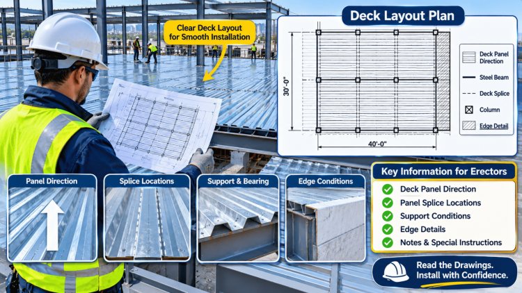
A deck layout drawing is not a design document—it is a field execution document. Every line, callout, dimension, and schedule on the page has a direct consequence for what the erector does, in what sequence, and with what hardware. Erectors who know how to read these drawings critically—not just follow them passively—catch coordination conflicts before they become installed errors. The four areas below represent the highest-value reading targets on any deck layout sheet.
Verify orientation, bearings, fastening zones, penetrations, piece marks, section details, and erection sequence to prevent installed errors and costly rework.
Erection Drawings That
Control the FieldRead the layout critically before the first panel is set.
The goal of every deck layout drawing package is to eliminate ambiguity before the first panel is set. When the drawing package is truly complete, the erector's job becomes execution rather than problem-solving. That shift in cognitive load directly translates to faster installation, fewer RFIs, and a handoff to the concrete or roofing trade that is clean, documented, and defensible.
A complete shop set acts as the single source of truth for the entire deck installation scope. These items are all resolved on paper before they become field decisions:
When an erector, inspector, or owner's representative has a question, the answer is on the drawing — not in someone's memory or an email thread.
The Consac workflow bridges the gap between contract design intent and fabrication/erection reality using model-based analysis and systematic discrepancy checks. Rather than passing design documents directly to the shop, detailers interrogate the structural model before the first detail is drawn for:
All of this happens before the discrepancy reaches the shop drawing. This upstream quality control is what keeps revision cycles short and RFI counts low.
When the drawing package is complete before detailing proceeds, erectors spend less time problem-solving and more time installing. This is not a philosophical statement — it is a measurable outcome. Crews that receive a complete, coordinated deck layout set with resolved details and clear fastening schedules consistently outperform crews working from incomplete sets on:
The investment in a thorough pre-detailing input gate and a disciplined drawing review process pays back in field productivity and reduced liability exposure for every party on the project.
A deck layout drawing package is only complete when every erector question that could arise in the field has already been answered on the page. Anything less is an incomplete document — and an avoidable risk.
The Payoff: Clean Installation & Zero-Error Handoff
Single Source of Truth
Model-Based Analysis & Discrepancy Resolution
Less Problem-Solving, More Installing
What's Your Reaction?