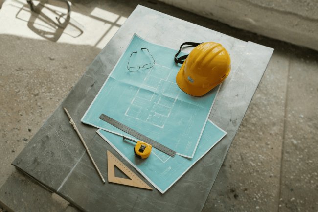
Deck Layout Planning for Multi-Bay Commercial Projects
Efficient deck layout planning is the backbone of any successful multi-bay commercial structure. From bay spacing decisions and span optimization to coordinating steel joists with deck orientation, every choice made early in the design phase cascades through cost, schedule, and structural performance. This presentation walks structural engineers, design managers, and construction planners through the critical decisions that define a high-performing deck layout — grounded in practical field knowledge and proven design methodology.

Understanding Bay Geometry & Span Strategy
The geometry of a multi-bay commercial project is the single most consequential variable in deck layout planning. Bay spacing — typically ranging from 20 to 40 feet in commercial applications — directly determines joist depth, deck gage, and the quantity of primary framing members. Selecting the optimal bay size requires balancing structural efficiency against architectural flexibility and mechanical routing needs.
Bay Spacing Fundamentals
Wider bays reduce column count and open interior space but demand deeper joists and heavier deck gages. Narrower bays reduce joist depth but increase framing complexity and material tonnage. For most commercial office and retail applications, 30-foot bays represent the sweet spot, achieving economy of scale in both framing and deck material without pushing joist depths into impractical ranges.
Always verify bay geometry against column grid coordination documents and façade module requirements before committing to a framing plan.
Span decisions made at SD phase are extremely difficult to reverse in CD — lock in bay geometry before advancing design.
Successful deck layout begins with bay geometry. Once spacing, span direction, flute orientation, and joist strategy are aligned, structural efficiency and constructability follow naturally.
Once bay geometry is established, the next critical decision is deck orientation — specifically, which direction the flutes run and how that interacts with primary framing, joist layout, and slab behavior. This decision has structural, constructability, and cost implications that ripple across every subsequent design phase.
Metal deck flutes must run perpendicular to supporting joists in composite and non-composite floor systems. This orientation allows the deck to bear directly on joist top chords, provides the correct shear transfer plane for composite action, and ensures proper concrete bearing width at deck ends. Running flutes parallel to joists — a common coordination error in multi-bay projects with irregular grids — creates bearing failures and requires costly supplemental framing. Confirm orientation in the framing plan before issuing for fabrication. For detailed detailing guidance, see steel joist detailing best practices.
Efficient panel layout minimizes field cuts, reduces waste, and accelerates erection. Key layout rules include: maintain a minimum 1.5-inch end bearing at supports; stagger side laps to avoid threesheet lap conditions; and plan sheet end joints to occur at framing members whenever possible. In multi-bay projects, establish a consistent deck module from a reference grid line and carry it through all bays — this prevents the accumulation of small dimensional errors that force nonstandard cuts at perimeter conditions.
Mechanical, electrical, and plumbing penetrations must be coordinated against the deck layout before shop drawings are issued — not after. In multi-bay commercial projects, MEP risers, elevator shafts, and stairwells create recurring opening conditions that, if uncoordinated, result in field-cut deck, unplanned header framing, and slab reinforcement additions. Build a composite coordination drawing that overlays deck panel layout against MEP rough-in locations. Review Consac's full resource library for coordination workflow references across disciplines.
Define bay geometry and layout
Align penetrations with structure
Choose flute direction and panel layout
Deck Orientation, Flute Direction & Layout Coordination
Flute Orientation Relative to Joists
End Lapping, Side Lapping & Panel Layout
Opening Coordination in the Layout Phase
Establish Bay Grid
Coordinate Openings
Set Deck Orientation
Structural performance in multi-bay commercial deck systems depends on three closely connected elements: gravity load distribution, camber coordination, and diaphragm continuity. These systems must be addressed during layout planning and structural design, rather than being deferred to fabrication drawings or field modifications where changes become significantly more expensive.
Tributary area assumptions directly influence joist selection and framing efficiency. In projects containing unequal bay widths, varying occupancies, and mixed-use floor plans, load paths must be documented explicitly rather than relying on averaged assumptions.
Structural framing plans should clearly show tributary width relationships and account for superimposed dead loads such as raised floors, topping slabs, equipment platforms, and mechanical systems. Early coordination minimizes redesign after framing selections are complete.
Camber is intended to offset anticipated dead-load deflection, but its effectiveness depends on coordination between adjacent framing members and neighboring bays. Excessive variation between adjoining cambered members can create visible floor profile irregularities after slab placement.
Camber requirements should be shown directly on framing plans rather than buried in specifications. A pre-pour survey requirement allows teams to verify compliance and identify potential elevation discrepancies before concrete placement begins.
The steel deck diaphragm serves as the primary mechanism for distributing lateral forces to shear walls, moment frames, and braced frames. Multi-bay structures require continuous force transfer across framing grids, transitions, openings, expansion joints, and irregular building geometries.
Diaphragm detailing must be planned intentionally rather than assumed through generic fastening requirements or repetitive standard details.
Specify deck attachment patterns directly from diaphragm analysis results rather than relying on generic fastening notes.
Show drag struts and collector elements directly on framing plans to clearly communicate force-transfer paths.
Provide explicit force-transfer details and continuity requirements at all expansion-joint interfaces.
Confirm deck gauge selected for gravity loading also satisfies diaphragm shear demands or increase gauge where required.
Gravity framing, camber strategy, and diaphragm performance cannot be treated as independent design tasks. Modifications to one system often affect the others through changes in stiffness, support conditions, attachment requirements, and construction sequencing. Projects that coordinate these systems during early design stages experience fewer RFIs, fewer structural revisions, and better alignment between structural, architectural, and construction documents.
Successful multi-bay deck design begins with a comprehensive understanding of load paths, deflection control, and lateral-force transfer. By documenting tributary loading assumptions, coordinating camber across adjacent framing systems, and detailing diaphragm continuity before shop drawing development begins, project teams create a more predictable, efficient, and structurally reliable building system. The most expensive diaphragm and framing problems are rarely engineering problems—they are coordination problems that should have been resolved upstream.
Load Distribution, Camber Strategy & Diaphragm Continuity
Gravity Load Distribution Across Bays
Camber Specification & Verification
Diaphragm Continuity in Multi-Bay Systems
Critical Diaphragm Planning Requirements
Attachment Design
Collector Elements
Expansion Joints
Gauge Verification
Why Early Coordination Matters
Final Engineering Takeaway
A structurally sound deck layout that cannot be built efficiently, or that creates conflicts with the construction sequence, will cost the project in field labor, schedule delays, and RFI volume. Constructability review of the deck layout is not optional — it is a core deliverable of the planning phase in any multi-bay commercial project.
Deck erection sequence must align with the steel erection sequence. In multi-bay projects, cranes typically work from one end of the building toward the other, and deck installation follows immediately behind steel erection to provide a working platform for subsequent trades.
Layout planning should minimize non-standard panel configurations in early bays — reserve complex edge and opening conditions for later bays when the erection crew is fully productive.
Deck shop drawings cannot be completed until framing plans, joist shop drawings, and structural notes are finalized and released. In multi-bay projects, this coordination chain is frequently the critical path item for deck procurement.
Establish a shop drawing submission schedule that accounts for all upstream deliverables and build in review time for multi-discipline coordination comments. Late shop drawing approvals on deck are one of the most common causes of concrete pour delays on commercial projects.
Reference Consac's joist detailing guidance to align joist and deck shop drawing workflows.
Key field verification checkpoints for multi-bay deck layouts include:
Assign accountability for each checkpoint to a named inspection party in the quality plan. Do not rely on general “special inspections per IBC” language — specify exactly what is being inspected and when.
Detailed pre-pour checklists, referenced against the layout plan, dramatically reduce pour-day RFIs and non-conformance reports.
For deeper resources on steel deck and joist coordination, visit Consac's Joist & Deck resource hub and explore the full technical library at consac.com/blogs.
Explore consac.com/blogs Constructability, Sequencing & Key Takeaways
Erection Sequence Planning
Shop Drawing Coordination Milestones
Field Verification & Quality Control
Numbers to Remember
What's Your Reaction?