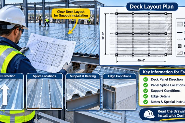
Deck Layout Planning Around Building Grid Irregularities
Structural steel framing rarely delivers a perfectly uniform grid. Stepped footprints, angled bays, re-entrant corners, and column offsets are routine realities on commercial and industrial projects — and each one demands deliberate deck layout decisions that go well beyond running standard panels from bearing to bearing. When irregularities are addressed late in the design process, the consequences compound: field-cut waste accumulates,end-lap conditions multiply unexpectedly, joist spacing shifts mid-bay, and sidelap fastener schedules become inconsistent. Getting ahead of these challenges during the layout planning phase is what separates an efficient, code-compliant installation from a costly rework cycle.
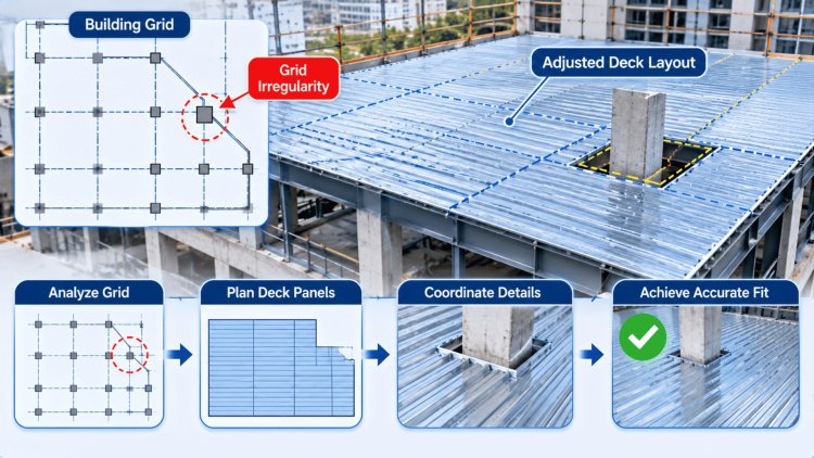
Understanding the Grid Problem: What Makes a Building Grid "Irregular"
Common Grid Irregularities Encountered in Practice
Non-rectangular bays
Skewed column lines or non-orthogonal grids where deck panels cannot run parallel to both supports simultaneously
Variable bay widths
Inconsistent spacing between column lines that prevents a uniform panel layout from repeating across the floor plan
Re-entrant corners
L-shaped, T-shaped, or U-shaped building footprints that create internal corners requiring custom closures and special bearing conditions
Column offsets and transfers
Columns that shift between floors, introducing transfer framing that disrupts the deck's natural span direction
Stepped or tiered floors
Elevation changes mid-plate that require horizontal diaphragm discontinuities to be explicitly detailed
Angled exterior walls
Facade lines that cut across the deck field at acute angles, generating non-standard edge trim and perimeter closure conditions
Why These Conditions Demand Early Layout Attention
A standard rectilinear bay allows the detailer to establish a panel module, set an end-lap location, and repeat the pattern across the entire floor plate with minimal variation. Irregular grids break that repeatability. Each deviation from the standard grid introduces at least one — and often several — unique conditions that must be individually resolved in the shop drawing package.
The structural engineer's role is to establish the deck's design criteria: span direction, diaphragm requirements, bearing minimums, and attachment schedules. The detailer's role is to translate those criteria into a panel layout that actually works in the field. When grid irregularities are present, these two roles must overlap earlier and communicate more explicitly than they would on a uniform-grid project.
Failing to identify irregular conditions during preliminary layout means those conditions will be discovered during fabrication or — worse — during installation. Field modifications to steel deck are time-consuming, produce scrap, and can compromise diaphragm continuity if not properly re-engineered. Early identification is the single highest-leverage intervention available.
Rule of thumb:
Flag any bay where column spacing varies by more than 6 inches from the nominal module as a "special condition" requiring individual layout review before panel count is finalized.
Panel orientation is the foundational decision in any deck layout, and it becomes significantly more consequential when the building grid is irregular. The goal is to maximize the number of panels that bear fully on their primary supports while minimizing the total length of field-cut edges, closure conditions, and special bearing details.
Treat irregular bays as subordinate infill conditions, document every non-standard end lap, verify skewed bearing, and explicitly engineer re-entrant-corner force transfer.
Panel Orientation Strategy:
Choosing the Right Span DirectionLet the dominant bay govern the span—not the exception.
Irregular framing conditions introduce some of the most challenging detailing scenarios in steel deck construction. Skewed supports, transfer framing, non-orthogonal facades, and modified diaphragm geometries require a higher level of engineering review than standard bay conditions. Successful detailing depends on validating bearing capacity, closure geometry, and diaphragm fastening requirements long before materials reach the field.
Minimum bearing requirements should be verified using the projected bearing width perpendicular to deck span rather than relying solely on nominal support-member dimensions. Skewed supports frequently reduce effective bearing conditions despite adequate flange width.
Transfer beams and girders created by column offsets introduce localized support conditions that often differ from the surrounding framing system. Deck layouts should explicitly identify end-laps, support transitions, and elevation adjustments associated with these framing shifts.
Curved and angled building envelopes frequently require custom closure profiles. Standard square-cut closure components rarely satisfy irregular façade geometries without modification.
Diaphragm performance depends on maintaining the fastening pattern assumed by design calculations. Irregular panel widths and modified end-lap conditions can significantly influence connection density and shear-transfer behavior.
Standard details should never be copied directly into irregular bays without verification. Changes in support orientation, panel geometry, framing alignment, or edge conditions often modify bearing requirements, closure configurations, and diaphragm fastening behavior. Successful detailing depends on evaluating these conditions individually and documenting all required modifications before fabrication release. The geometry changes, the load path changes, and the detailing must change accordingly.
Bearing, Closure, and Fastener Coordination at Irregular Conditions
Bearing Width Verification
Column Offset & Transfer Framing
Perimeter Closure & Edge Trim
Fastener Schedule Consistency
Irregular Condition Verification Process
Critical Coordination Checks
Key Detailing Principle
Successful deck layout on irregular-grid buildings is as much a coordination discipline as it is a technical one. The following checkpoints and principles consolidate the key practices that experienced detailers and structural engineers should build into their standard workflow on any project where the grid deviates from uniform orthogonal framing.
Identify grid irregularities before layout begins — not during shop drawing review
Verify projected bearing width at every skewed or offset support
Re-check diaphragm fastener schedules in every non-standard bay
Engineer re-entrant corners explicitly — do not rely on slab continuity alone
Use shop-fabricated closures at angled perimeters where possible
Document all exceptions with located callouts, not general notes
Coordinate with the engineer of record before releasing irregular-bay shop drawings
The topics covered in this presentation are part of a broader body of technical guidance available through the Consac blog series on deck and joist detailing. Related topics — including deck opening behavior, joist seat detailing, and diaphragm attachment at penetrations — are covered in adjacent posts in the series. For project-specific questions on irregular-grid deck layout, the Consac team provides direct technical support to engineers and detailers working on complex structural packages.
When in doubt on a specific irregular condition, the most effective path is a direct conversation between the detailer and the engineer of record, with the specific geometry in front of both parties. No general guidance document — including this one — substitutes for a project-specific engineering judgment on a unique framing condition. Use these principles as a framework for structuring that conversation efficiently, with the right questions asked at the right phase of the project.
Coordination Checkpoints and Practical Takeaways
Key Principles to Carry Forward
Further Resources
What's Your Reaction?