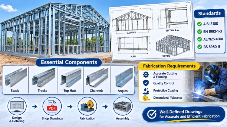
Light Gauge Steel Shop Drawings: Essential Components, Standards & Fabrication Requirements
Shop drawings are the backbone of every successful light gauge steel (LGS) project. Far more than simple blueprints, CFS shop drawing services translate architectural intent into precise, fabrication-ready documentation that guides every cut, punch, and screw on the job site. Whether you're a structural engineer reviewing connection details, a fabricator programming a rollforming machine, or a project manager coordinating submittals, understanding what goes into a complete set of LGS shop drawings is essential for quality control, schedule adherence, and cost certainty.
Interpreting Architectural & Structural Documents
The first — and most critical — phase of producing LGS fabrication drawings is the accurate interpretation of architect-issued and engineer-of-record (EOR) documents. This requires reconciling architectural drawings, structural calculations, geotechnical reports, and project specifications into a single, coordinated framing package. Errors at this stage cascade into costly field modifications, submittal rejections, and schedule delays.
Architectural Drawing Interpretation
Our drafters cross-reference floor plans, reflected ceiling plans, exterior elevations, and wall sections to establish stud heights, header configurations, and partition layouts. Special attention is paid to deflection track requirements at non-load-bearing conditions, curtain wall interfaces, and fire-rated assembly specifications that dictate stud gauge, spacing, and sheathing requirements.
Openings for doors, windows, mechanical penetrations, and service chases are identified early to allow proper cripple stud, king stud, and header design — all documented per Digiverse Studio's standardized detail library.
Structural Drawing Coordination
Structural drawings define load-bearing wall lines, shear wall locations, hold-down anchor positions, and point load transfer paths. Our engineers verify that the framing layout accommodates every gravity and lateral load demand identified by the EOR, including load path continuity from roof to foundation.
Critical checks include stud stacking alignment between floors, rim track and bearing plate sizing, and the coordination of LGS members with concrete or masonry substrates at podium interfaces. Any discrepancy between architectural and structural documents is flagged via RFI before drawing production begins.
Why Early Document Interpretation Matters
Fabrication drawings are only as accurate as the information used to create them. Thorough document interpretation identifies conflicts, validates structural intent, coordinates architectural requirements, and establishes constructible framing solutions before production data is generated. Every issue resolved during coordination prevents exponentially greater cost and disruption during fabrication and field installation.
Successful LGS detailing begins long before panel design or shop drawing production. The ability to accurately interpret, coordinate, and reconcile architectural and structural intent is what transforms project documents into reliable fabrication-ready information.
The most valuable fabrication drawing work happens before the first stud is detailed. When architectural intent, structural requirements, and constructability constraints are aligned at the document review stage, the entire downstream workflow becomes faster, more accurate, and more predictable.
A complete LGS shop drawing set includes fully dimensioned framing plans for every level of the structure. These drawings are the primary production documents used by fabricators and framers alike, and their accuracy directly determines field efficiency.
Exterior and interior wall layouts identify stud size, gauge, and spacing (typically 16" or 24" o.c.), along with track sizes, corner and intersection configurations, and stud height callouts. Loadbearing walls are clearly distinguished from non-load-bearing partitions using standardized line weights and symbology. Balloon-frame conditions at stair shafts and vaulted spaces receive dedicated detail sheets addressing bridging, blocking, and lateral bracing requirements.
Floor joist layouts indicate member size (e.g., 600S200-54, 800S200-68), spacing, bearing length, and web stiffener requirements at point loads. Roof framing plans coordinate rafter or truss layout with ridge beam, hip, and valley members, including required blocking at eaves and gable ends. All cantilevers, openings, and concentrated load zones receive explicit reinforcement callouts per AISI S240 provisions.
Comprehensive member schedules list every unique stud, track, joist, and header with its AISI designation, yield strength (typically 33 ksi or 50 ksi), length, quantity, and any factory-punched web openings. Dimensions are provided in both plan and elevation views, fully toleranced for field installation. Each member is tagged to its fabrication schedule, enabling direct traceability from drawing to cut list.
Connection details show screw type, quantity, pattern, and placement at every structural joint — including stud-to-track, header-to-king-stud, joist-to-rim-track, and hold-down-to-stud interfaces. Details reference AISI S100 Table J4 screw capacities and are coordinated with engineer-stamped connection calculations. Welded connections, where permitted, include weld size, length, and electrode specification per AWS D1.3.
Wall, Floor & Roof Framing Layouts — Member Schedules & Connection Details
Wall Framing Plans
Floor & Roof Framing Plans
Member Schedules & Dimensions
Connection Details
The precision embedded in screw patterns, reinforcement details, and fabrication schedules is what separates a good LGS shop drawing package from a great one. These details directly govern factory production output, field labor efficiency, and structural performance under service loads.
Explicit fastener patterns, engineered opening schedules, and BOM-correct fabrication lists improve factory throughput, field efficiency, and structural performance.
Screw Patterns, Openings, Reinforcements
& Material Fabrication SchedulesDetail every screw, opening, reinforcement, and cut before fabrication.
The final — and most technically demanding — stage of the LGS shop drawing process is converting engineering documentation into machine-readable production files and completing the multi-layer quality review required before fabrication approval. This stage determines whether the investment in precise drafting pays dividends on the shop floor.
Modern CFS fabrication relies on automated rollforming lines controlled by software platforms such as:
The shop drawing workflow generates export files directly from the drawing database:
Before any drawing set is released for fabrication, it passes through a structured multi-stage QA review.
The checklist is aligned with AISI S240 and project specification requirements. A senior engineer then performs a final structural review against the EOR's calculations.
Only after digital sign-off is the package issued, ensuring zero ambiguity at the shop floor level.
From the first document review to the final fabrication approval stamp, a rigorous steel framing detailing workflow ensures every panel, member, and connection is precisely documented, fully coordinated, and production-ready.
From Shop Drawings to Machine-Ready Outputs & Pre-Fabrication Quality Checks
Converting to Machine-Ready Outputs
Web punch locations
Notch dimensions
Label data
.xml
Proprietary machine formatsQuality Checks Before Fabrication Approval
What's Your Reaction?