Steel Deck Detailing for Mechanical Platforms
Mechanical platforms introduce a distinct set of structural and detailing challenges that go well beyond standard floor deck applications. Unlike typical composite floor systems, these elevated platforms must simultaneously support heavy rotating equipment, accommodate dense MEP routing, endure vibration and thermal cycling, and remain accessible for maintenance — all within tight spatial and load constraints. This presentation distills the critical detailing decisions that structural and mechanical detailers, BIM coordinators, and engineers must navigate to produce accurate, buildable, and code-compliant mechanical platform packages.
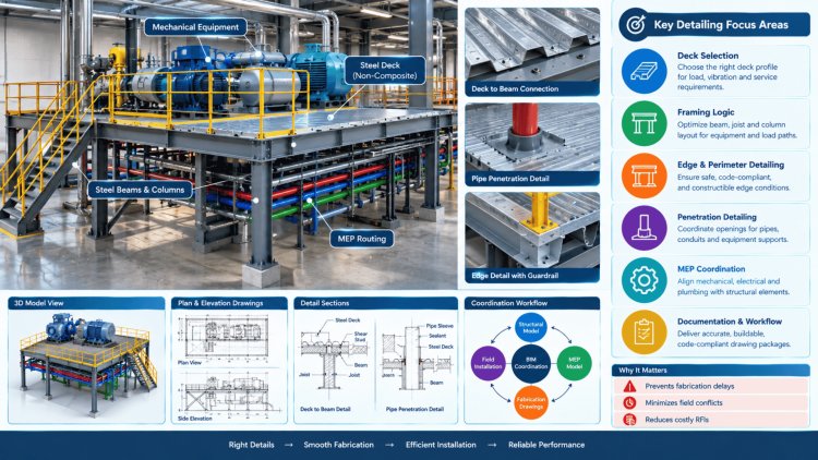
Deck Selection & Structural Framing Fundamentals
Selecting the correct deck profile and framing arrangement for a mechanical platform is the foundational decision from which all subsequent detailing flows. Mechanical platforms carry concentrated point loads from equipment, dynamic loads from rotating machinery, and distributed loads from piping and gratings — load profiles that differ substantially from typical office or residential floor decks.
Profile Selection, Framing Geometry, and Connection Design Form One Structural System
Profile
Framing
Performance
Deck Profile
Considerations
For mechanical platforms, 1.5" Type B (wide rib) or 3" deep deck profiles are most common. Deeper profiles provide greater unshored span capacity and stiffer sections, which help attenuate vibration transmission to equipment supports. When access grating must interface with the deck, coordinate the rib orientation early — flutes running parallel vs. perpendicular to the primary framing members significantly affect puddle weld patterns and bearing conditions.
Profile Depth Influences Span and Vibration Performance
Deck May Be the Primary Structural Element
Non-composite deck is frequently specified for mechanical platforms where the topping slab is thin or absent — particularly on rooftop mechanical units where a structural slab is replaced by equipment pads. In these cases, the deck acts structurally in flexure alone, and section properties must be verified against the full unfactored dead plus live load combination without composite action credit.
Match Structural Framing to Equipment Footprints
Framing Geometry & Camber
Camber is often reduced or eliminated on mechanical platform beams because excessive upward deflection under dead load alone can cause equipment leveling problems. Confirm camber requirements with the mechanical engineer, especially for sensitive rotating equipment with strict alignment tolerances. A common practice is to specify zero camber on beams supporting chillers, air handlers, or pump skids.
Confirm Camber Requirements Early
Deck-to-Frame Attachment
Puddle weld schedules must reflect the actual uplift and shear demands at the deck-to-joist or deck-to-beam interface. On mechanical platforms exposed to wind uplift (rooftop applications) or to vibration-induced fatigue, weld spacing should be rationalized against the SDI deck specification for the applicable design category — not defaulted to a standard pattern used for interior floor decks.
Side-Lap Fastening
Button-punch or screw side-lap fasteners must be explicitly called out in the deck erection plan. On mechanical platforms with high diaphragm shear demands — common in rooftop platforms braced against equipment lateral loads — the side-lap fastener pattern directly influences the diaphragm shear capacity used in design. Coordinate with the structural engineer of record before substituting fastener types or spacing.
Side-Lap Fasteners Influence Diaphragm Capacity
Select the Right Deck. Coordinate the Framing. Control the Connections.
Edge and penetration detailing represents the highest concentration of RFI-generating conditions on mechanical platform projects. Compound geometry must be fully resolved in the model before fabrication.
Edge Conditions, Penetrations &
Equipment CurbsEdge Detailing Decision Path
Detailed resolution of deck penetrations and equipment curbs is paramount for mechanical platforms. These elements are not merely functional but critical structural interfaces, requiring precise detailing to ensure integrity, prevent leaks, and facilitate equipment installation and maintenance.
Mismanagement of penetrations, curbs, and large openings frequently leads to extensive field modifications and costly delays.
Any opening exceeding one deck rib width necessitates header framing. Detail with structural angles or channels, incorporating trimmer angles and cripple framing to adequately transfer loads and maintain deck diaphragm capacity.
Coordinate the framing so opening loads are transferred appropriately and the deck diaphragm's capacity is maintained.
Proactive coordination with MEP trades is non-negotiable. Finalize penetration locations, sizes, and any required offsets with mechanical, electrical, and plumbing teams well before deck installation to avoid conflicts and field cutting.
Confirm penetration positions.
Verify opening sizes.
Resolve required service offsets.
Resolve conflicts before deck installation.
Detailing principle: Resolve structural support, equipment loading, waterproofing, and MEP requirements together before installation to reduce field modifications and costly delays.
Penetrations, Curbs, & Large Openings
Every Opening Must Work With the Deck System
Large Openings
MEP Coordination
Ensuring the long-term performance and structural integrity of mechanical platforms requires meticulous attention to vibration control during design and rigorous quality assurance throughout construction. Proactive planning helps mitigate potential issues that can lead to costly retrofits or operational disruptions.
Structural analysis for mechanical platforms must include dynamic checks to prevent resonance between the platform's natural frequency and the operating RPM of rotating equipment. This involves comparing the calculated natural frequencies of the deck and supporting structure against equipment specifications.
Early detection of potential resonance issues allows for design modifications such as increasing stiffness, adjusting framing geometry, adding supplemental bracing, or selecting alternative deck profiles. These measures help ensure a stable, compliant, and serviceable platform throughout its operational life.
Utilize federated BIM models to perform comprehensive clash detection between structural steel, mechanical equipment, and deck penetrations. Resolve spatial conflicts proactively to eliminate field modifications and installation delays.
Regularly federate architectural, structural, and MEP models to establish a complete project view. Conduct interdisciplinary reviews to ensure all components are represented accurately and coordinated before detailing begins.
Implement a structured RFI management process within the BIM environment. Track all coordination issues, monitor responses, and close outstanding items promptly to maintain design intent and avoid construction delays.
Verify all shop drawings for deck, joists, equipment supports, framing members, and connection details against the approved design documents. Particular attention should be given to weld requirements, bolt patterns, support conditions, member sizes, coating specifications, and any deviations from standard detailing practice.
Conduct comprehensive field inspections covering weld quality, deck attachment patterns, puddle weld installation, mechanical fastener placement, penetration sleeves, equipment anchor locations, and framing tolerances.
Confirm that all installed components match approved shop drawings and satisfy project tolerances. Early identification of discrepancies prevents detailing errors, minimizes rework costs, and protects structural performance.
Vibration Control & QA/QC for Mechanical Platforms
Vibration Analysis Considerations
BIM Coordination Workflows
Clash Detection & Resolution
Model Federation & Review
RFI Management & Tracking
Shop Drawing Review
Field Inspection Items
Critical Mechanical Platform Verification Checklist
What's Your Reaction?