Deflection Track Detailing in Light Gauge Steel

Managing Floor Movement & Wall Stability in Cold-Formed Steel Framing Head-of-Wall Connections, Vertical Movement, Lateral Stability, Fire-Rated Assemblies.
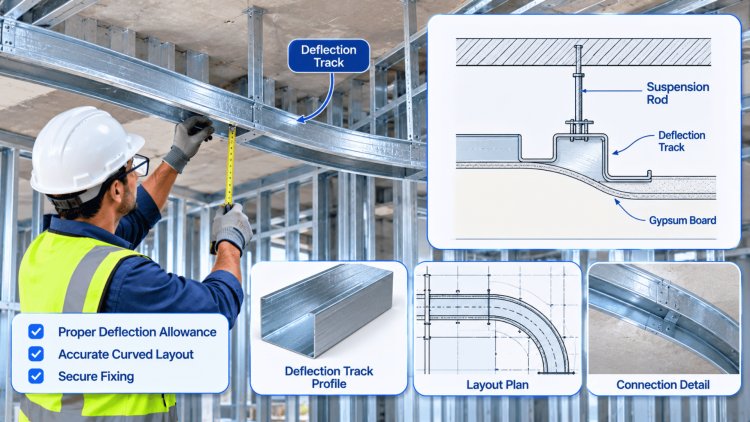
Deflection Track Detailing in Light Gauge Steel
Light Gauge Steel Wall Systems

Understanding Deflection Tracks & Their Purpose

What Is a Deflection Track?

A deflection track — also called a slip track or slotted head track — is a specially configured cold-formed steel (CFS) runner installed at the top of a non-load-bearing partition wall. Unlike a standard CFS track, the deflection track does not rigidly connect the top of the wall studs to the overhead structure.

Instead, it allows the studs to slide vertically within the track's web, decoupling the partition from the structural floor or roof assembly above.

This decoupling is essential because concrete slabs, steel beams, and composite deck assemblies all deflect under live load, creep, and thermal cycling. Without relief, these movements transfer directly into the partition, inducing bending stress in studs, cracking gypsum board, and compromising door frame geometry.

Why It Matters Structurally

IBC and AISI S200 require non-load-bearing partitions to accommodate the vertical movement of the structure above without transferring axial load into the wall system. Deflection tracks provide a compliant mechanism for this requirement.

The design engineer must specify the anticipated live-load deflection (LL) and total load deflection (TL) of the spanning assembly and ensure the track leg depth and slot length are sufficient to absorb the full range of movement.

A common industry requirement is to provide a minimum additional clearance of 1/2 inch beyond the calculated deflection value to ensure unrestricted movement throughout the life of the structure.

How the System Works

Structural floor or roof deflects under live load, creep, or thermal movement
Deflection track allows wall studs to move vertically without carrying building loads
Gypsum board, doors, and finishes remain protected from compression damage
Lateral stability of the partition is maintained while vertical movement remains unrestricted

Key Design Parameters

Anticipated Floor/Roof Deflection

Live-load deflection, long-term creep, and structural movement must be fully accommodated.

Track Leg Height

The track depth must provide adequate travel distance while maintaining stud guidance.

Slot Length

Slots must allow the full anticipated movement range plus required design clearance.

Lateral Load Demand

Head-of-wall connections must resist required lateral forces without restricting movement.

Fire & Acoustic Requirements

Deflection assemblies must maintain required fire-resistance and acoustic performance ratings.

Common Consequences of Improper Design

Cracked gypsum board at head-of-wall joints
Buckled or overstressed wall studs
Misaligned door frames and operational issues
Fire-rated assembly failures due to restricted movement
Increased maintenance and repair costs throughout building service life

Deflection tracks are not optional accessories. They are engineered movement joints that protect non-load-bearing partitions from structural deflection, preserve architectural finishes, and maintain code-compliant wall performance throughout the life of the building.

Successful CFS wall design recognizes a fundamental reality: buildings move. Deflection tracks provide the controlled flexibility required to accommodate that movement while preserving structural integrity, finish quality, fire resistance, and long-term performance.

Head-of-Wall Connection Systems & Slotted Track Types

The head-of-wall (HOW) detail is one of the most critical — and most frequently mis-detailed — nodes in CFS construction. The connection must simultaneously resist in-plane lateral loads (bracing the stud against racking) while permitting free vertical translation of the stud within the track. Several system types exist, each with distinct performance characteristics and installation requirements.

1

Standard Slotted Track

The most common deflection track type. Vertical slots are factory-punched into the track web at each stud location. The stud is inserted into the track and fastened with a single screw at the midpoint of the slot — never at the top or bottom — allowing the stud to travel upward or downward within the slotted range. Typical slot lengths are 1-1/2 in. or 2 in., though extended slot tracks are available for high-deflection applications up to 3-1/2 in. The lateral load is transferred via bearing of the stud flanges against the track flanges, not through the fastener itself.

2

Clip-Based & Proprietary Sliding Systems

For higher-movement environments or seismic zones, proprietary sliding clips — such as the CEMCO SlipClip® or ClarkDietrich Sliptrack® — replace the slotted screw connection with a formed clip that positively engages the stud flange while providing a guided vertical travel path. These clips resist lateral load more reliably than a single fastener in a slot and are preferred where calculated drifts exceed 1 in. or where the wall must also resist out-of-plane wind or seismic loads at the head. Clip systems often carry ICC-ESR evaluation reports validating their load and movement ratings.

3

Telescope Track (Double-Track) System

Used where extremely large deflections or story drift must be accommodated — often at the top of tall partitions in atrium or high-bay spaces. Two nested tracks form the head assembly: the outer track is fastened to the structure above; the inner track is fastened to the stud. As the floor deflects, the inner track telescopes within the outer. This system requires careful coordination of track leg sizes and tolerances and must be detailed to prevent binding under combined gravity and lateral load scenarios.

4

Flexible Gypsum Joints at the Head

Regardless of which track system is used, the gypsum board must be detailed to accommodate the same vertical movement. Standard practice is to terminate gypsum board 3/8 in. to 1/2 in. short of the deflection track flange and fill the gap with a code-approved, paintable, fire-rated flexible sealant. This joint — often detailed as a "fire caulk gap" — allows the board to remain stable while the track travels. Failure to provide this relief is the single most common cause of partition cracking and fire-rating void in CFS-framed buildings.

CFS Deflection Track Design

Maintaining Lateral Stability
While Allowing Vertical Movement

The core engineering tension in deflection track design is providing lateral restraint at the head of wall—required by code for stud stability and in-plane diaphragm transfer—without introducing a rigid axial connection that would load the stud in compression as the floor deflects. This is a compatibility problem: the lateral load path must be stiff, while the vertical load path must be soft.

Head-of-wall compatibility

Lateral Restraint Without Vertical Load Transfer

Requirement 01
AISI S211 Lateral Bracing
AISI S211 (Standard for CFS Framing—Wall Stud Design) addresses this directly, requiring that non-load-bearing studs be laterally braced at both ends. At the head, that brace must be provided without transferring vertical load. The fastener-in-slot method accomplishes this through bearing, but the designer must verify that the bearing capacity of the slot edge—not the fastener shear—is the governing limit state.
Requirement 02
Seismic & Wind Load Considerations
In Seismic Design Categories C through F, story drift demands at the HOW connection can reach 1 in. or more. Standard slotted tracks with 1-1/2 in. slots may be insufficient. The structural engineer must coordinate the calculated story drift with the wall engineer and specify the minimum required slot travel on the construction documents. Additionally, out-of-plane wind pressure on the wall face is transferred through the stud to both the base track and the head track—the fastener or clip at the head must be sized for this lateral demand independent of the vertical deflection function.
Bracing strategy at mid-height

For Studs Taller Than Approximately 12 ft. or Where H/t Exceeds AISI Limits

Method 01
Bridging Channels
Bridging channels clipped or welded across the stud flanges and anchored to structure or shear walls at intervals not to exceed 12 ft.
Method 02
Flat Strap X-Bracing
Flat strap X-bracing applied to the stud face and anchored at the floor or ceiling track.
Method 03
Blocking Tracks
Blocking tracks (continuous horizontal tracks) installed in the stud cavity at mid-height, fastened to each stud flange.
Coordination note for fire walls

Listed Assemblies, Tested Alternatives, and AHJ Equivalency

Requirement 01
At rated fire walls and fire barriers, the head-of-wall assembly must be listed—not just engineered—for the required rating
Requirement 02
UL U-series and W-series assemblies, as well as GA-600 fire-resistance design manual details, provide prescriptive HOW details for 1-hr, 2-hr, and 3-hr rated partitions
Requirement 03
Any deviation from the listed assembly—including substituting a proprietary clip for a slotted screw—requires a tested, evaluated alternative or a letter of equivalency from the AHJ
Deflection track principle

Keep the lateral path stiff. Keep the vertical path soft.

Detail the head-of-wall connection to restrain studs laterally, accommodate story drift, resist wind demand, and preserve the listed fire assembly.

CFS Deflection Track Systems

Common Detailing Mistakes & Installation Best Practices

Deflection track systems are designed to isolate non-load-bearing partitions from vertical structural movement. However, even properly engineered systems regularly experience field failures due to installation mistakes, coordination oversights, and incomplete detailing. Preventing these issues requires clear documentation, disciplined field practices, and coordination between structural, architectural, and fire-protection stakeholders throughout the project lifecycle.

❌

Screwing Studs Tight to the Track

Fastening stud flanges rigidly to the deflection track eliminates the movement capability the system was designed to provide. Once a fixed connection is created, structural movement transfers directly into the partition assembly.

Best Practice
Follow specified slot-fastener installation requirements and verify movement allowances during framing inspections.
❌

Insufficient Track Leg Depth

Deflection movement requirements must be evaluated against available slot travel and stud engagement. Standard track profiles may not provide sufficient movement capacity for larger anticipated building deflections.

Best Practice
Verify track geometry, leg depth, and slot length against calculated structural movement requirements.
❌

Rigid Gypsum Board Head Joints

Gypsum board attached rigidly within the deflection zone transfers structural movement directly into finished wall surfaces, often resulting in visible cracking and repeated repair cycles.

Best Practice
Provide the required movement gap and utilize approved flexible materials that accommodate expected deflection.
❌

Missing MEP Coordination

Mechanical, electrical, and plumbing systems crossing the movement zone can unintentionally create rigid load paths that bypass the deflection-track assembly and compromise performance.

Best Practice
Coordinate flexible connections, movement allowances, and fire-stopping systems within all penetration details.

Deflection Track Installation Verification

Slot Verification
Track Engagement
Gypsum Clearance
MEP Coordination

Project Team Best Practices

Detail the Entire Assembly

Document slot geometry, track depth, fastener requirements, gypsum clearances, movement allowances, and fire-seal systems explicitly.

Train Installation Crews

Ensure field personnel understand how deflection systems differ from conventional framing connections.

Verify During Inspection

Include movement-track compliance checks as a dedicated inspection activity rather than relying solely on visual framing reviews.

Coordinate Early

Align structural, architectural, wall-engineering, and fire-protection requirements during design development.

Final Takeaway

Deflection track systems are highly dependent on correct detailing and precise installation. Most failures are not caused by inadequate engineering but by small field deviations that compromise movement capability, fire resistance, or partition performance. The most successful projects coordinate requirements during design development, communicate them clearly through construction documents, and verify compliance through dedicated inspections. When properly detailed and installed, deflection tracks effectively protect partitions from structural movement while maintaining code compliance and long-term building performance.

What's Your Reaction?

like

dislike

love

funny

angry

sad

wow