Architectural Precast Facade Detailing: Panels, Embeds & Building Integration
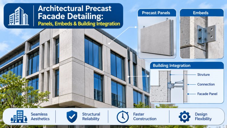
Precast concrete has long been a cornerstone of modern architectural expression — offering a rare combination of structural reliability, dimensional precision, and unlimited aesthetic versatility. For façade engineers, architects, and construction professionals, mastering the full spectrum of architectural precast façade detailing is essential to delivering projects that meet exacting performance, visual, and constructability standards.
Panel Systems, Geometry & Surface Finishes
A thorough understanding of architectural precast façade systems begins with the building blocks themselves — the individual panel units that collectively define a building's exterior character and performance.
Understanding Precast Façade Systems
Architectural precast façade systems function as the outermost envelope of a structure, providing weather resistance, thermal control, acoustic attenuation, and visual identity simultaneously. Panels are typically manufactured off-site under factory-controlled conditions, ensuring higher quality tolerances than cast-in-place alternatives.
Systems range from full-story spandrel panels to column covers, mullion panels, and large-format load-bearing units. Each system type carries its own structural assumptions, connection requirements, and detailing logic that must be thoroughly resolved during the shop drawing phase before panels reach the fabrication plant.
Geometry, Reveals & Returns
Panel geometry drives both the visual rhythm of the façade and the constructability of the system. Key geometric considerations include panel dimensions (typically limited by crane capacity and transportation constraints), reveal depth and width (which define shadow lines and visual scale), and return angles at panel edges.
Reveals — whether recessed, projected, or flush — are among the most impactful design decisions in precast wall panel detailing. Deep reveals require careful formwork design and must be evaluated for potential cracking at re-entrant corners.
Draft angles must be incorporated wherever panels narrow toward the mold face to allow clean stripping without surface damage.
Exposed Aggregate
Achieved through retarder application and washing, exposed aggregate finishes reveal the natural stone character of the mix. Aggregate size, color, and depth of exposure are critical specification variables that directly affect panel-to-panel consistency across the façade.
Sandblasted & Acid-Etched
These post-cure mechanical and chemical treatments remove the cement paste surface layer to varying depths, creating matte, uniform textures. Acid-etching produces finer texture profiles while sandblasting allows more aggressive surface relief — both require strict quality control protocols.
Form Liner Textures
Elastomeric and rigid form liners imprint geometric patterns, wood grain, stone coursing, or custom artwork directly into the panel face during casting. This approach allows highly repeatable surface textures without post-processing and is cost-effective for large panel quantities sharing the same mold.
Paint & Integral Color
Integral pigments dispersed through the concrete matrix provide color consistency that extends through the panel thickness — eliminating the aesthetic risk of paint delamination over time. Exterior-grade elastomeric coatings may be applied over any finish for additional weather protection and color uniformity.
Successful architectural precast design balances geometry, constructability, transportation limitations, surface aesthetics, and long-term durability. Panel proportions, reveal layouts, and finish selections should be resolved together so the architectural vision can be delivered consistently across the entire façade.
Architectural precast succeeds when panel geometry, reveal strategy, connection detailing, and surface finish selection work together to create a façade that performs as well as it looks.
The structural and functional intelligence of a precast façade lives largely in the details that are hidden from view — the openings cut through panel faces, the steel hardware cast into concrete, and the connection hardware that ties the entire system to the building structure.
Incorporating window and door openings into precast panels requires careful attention to several interacting design variables. Structurally, openings introduce re-entrant corners that concentrate stress — diagonal reinforcement bars (typically #4 or #5 at 45°) are placed at all four corners to control cracking under thermal movement and handling loads. Sill slopes must be incorporated into the panel geometry to drain water away from glazing interfaces, typically at a minimum 5% crossslope. Frame blockouts must be oversized by the specified tolerance — commonly ±1/4 inch — to allow window unit installation with adequate adjustment range. Precast façade shop drawings must clearly show the relationship between the blockout rough opening, the nominal frame size, the setting dimension, and the perimeter sealant joint width to ensure waterproofing continuity.
For punched openings in thin spandrel panels, the remaining concrete section at jambs must be evaluated for net section capacity under eccentric handling and erection loads. Where openings approach panel edges, the designer must assess whether additional thickened sections or internal steel frames are warranted to prevent cracking during stripping and transport.
Every precast panel must be positively connected to the building structure through engineered embed systems. Standard connection hardware includes headed stud assemblies welded to base plates, cast-in-place inserts (coil inserts, threaded ferrule inserts, or slotted channels), and post-installed anchors where cast-in items were omitted or relocated. Connection eccentricities — the offset between the panel's centroid and the structural bearing point — generate moments that must be accounted for in both the embed design and the structural frame design.
Bearing connections (typically two per panel) carry gravity loads and are designed with slotted holes in the horizontal plane to accommodate panel expansion. Lateral tie-back connections resist wind and seismic loads, and are typically slotted vertically to allow differential structural movement. All hardware must be hot-dip galvanized or stainless steel where exposed to weather, and corrosion protection continuity must be maintained through field welds using zinc-rich paint per AWS D1.1 requirements.
Support panel dead load and superimposed façade loads. Typically located at two points per panel near the bottom edge. Slotted horizontally for thermal movement. Seat angles or corbels welded or anchored to structural steel or concrete frame.
Resist out-of-plane wind pressure and seismic forces. Slotted vertically to allow story drift without transferring axial load into panels. Typically positioned near the top panel edge and coordinated with structural slab or beam locations.
Shims, leveling bolts, and slotted connections provide three-dimensional adjustability during erection — critical for achieving façade tolerances of ±1/4 inch in plane and ±3/8 inch overall. Final positions are confirmed by survey before permanent welding or bolting.
All steel embeds must comply with PCI MNL-117 and project-specific corrosion protection specifications. Hot-dip galvanizing per ASTM A123, stainless steel (316L minimum in coastal environments), or epoxy-coated systems are standard choices depending on exposure category.
Openings, Embedded Elements & Facade Connections
Window & Door Openings in Precast Panels
Embedded Plates, Anchors & Connection Hardware
Bearing Connections
Lateral Tie-Back Connections
Alignment & Adjustment Hardware
Corrosion Protection Requirements
One of the most demanding responsibilities in architectural precast detailing is achieving seamless integration between precast façade systems and adjacent building-envelope components. Curtain walls, storefront systems, louvers, roofing assemblies, air barriers, and thermal-control layers must function as a unified enclosure while remaining independently supported and fully coordinated before fabrication begins.
The transition between precast spandrel panels and curtain wall framing systems is often the most detail-intensive interface on mixed-envelope buildings. Air barriers, thermal-control layers, moisture management systems, and structural attachment requirements must all align while allowing independent movement of each building component.
Pressure-equalized sealant joints are commonly used between precast panels and curtain wall frames. Backer rods are typically sized to maintain an approximate joint depth-to-width ratio of 1:2, allowing the sealant system to perform effectively while accommodating building movement.
Curtain wall anchor locations must be coordinated against precast embeds, connection plates, panel joints, reinforcing steel, and fabrication tolerances to eliminate conflicts during installation.
Successful façade integration depends on early digital coordination between precast suppliers, curtain wall contractors, structural engineers, architects, and enclosure consultants. Federated BIM environments provide a common coordination platform where all interface conditions can be reviewed before production.
Scheduled clash-detection reviews allow teams to identify conflicts involving anchors, embeds, support brackets, mullions, reinforcement, waterproofing systems, and movement joints before fabrication begins.
Resolving these issues digitally reduces RFIs, field modifications, and installation delays while improving envelope performance.
Modern building energy regulations require continuous thermal and air-barrier systems throughout the entire enclosure. Architectural precast systems frequently achieve thermal performance through insulated sandwich panel construction, where a continuous insulation layer is captured between structural and architectural concrete wythes using thermally efficient connector systems.
At curtain wall and window transitions, the insulation layer must continue seamlessly into the glazing system's thermal-break assembly. Gaps in this transition can introduce thermal bridging, condensation risks, and reduced energy performance.
Air-barrier membranes applied to backup structures must extend beneath bearing locations and connect securely to the rear face of the precast system using flexible sealants capable of accommodating anticipated differential movement throughout the building lifecycle.
Federated models coordinate curtain wall framing, precast embeds, movement joints, and support systems.
Verify interface dimensions, tolerances, waterproofing details, and attachment locations before fabrication.
Confirm installed conditions satisfy design tolerances before glazing systems are installed.
Successful precast façade projects are won or lost at the interfaces. Curtain wall transitions, thermal-control layers, waterproofing systems, and structural attachments must be coordinated as a single integrated enclosure rather than as separate subcontractor responsibilities. Comprehensive BIM coordination, rigorous shop drawing reviews, and documented field verification procedures ensure every interface remains structurally sound, thermally continuous, and construction-ready long before the first panel or mullion reaches the jobsite.
Curtain Wall Coordination & Building Envelope Integration
Precast-to-Curtain Wall Interface
BIM-Based Coordination Workflow
Air Barrier & Thermal Continuity
Envelope Coordination Workflow
Critical Coordination Topics
Engineering Takeaway
The long-term performance of any precast façade system depends critically on the quality of its weatherproofing strategy. Panel joints, interface conditions, and sealant detailing must be engineered—not assumed—to ensure the façade remains watertight, thermally efficient, and structurally sound across its full design life of 50 years or more.
These are the definitive industry standards for precast connection design, panel detailing standards, and quality requirements for architectural and structural precast concrete in North America.
Weatherproofing, Joint Detailing
& Installation TolerancesConsult PCI MNL-117 and the PCI Design Handbook (8th Edition).
What's Your Reaction?