Precast Concrete Connection Design: Types, Details & Best Practices
In modern structural engineering, the integrity of a precast concrete structure depends not just on the quality of individual elements — but on the precision and reliability of the connections that bind them together. Precast concrete connection design is one of the most technically demanding disciplines in structural engineering, requiring a deep understanding of load transfer mechanisms, material compatibility, constructability constraints, and long-term durability. Whether you are detailing a multi-story parking structure, a precast wall panel system, or a bridge superstructure, the connections you specify will determine whether the structure performs as intended under service loads, seismic events, and thermal movements. This guide covers the full spectrum of precast connection detailing — from basic principles to advanced hardware selection — giving structural engineers and precast designers a comprehensive reference for best practice design.
Understanding Structural Connections in Precast Construction
Structural connections in precast construction serve a fundamentally different purpose than those in cast-in-place concrete. Because precast elements are manufactured off-site and transported to the job site, every interface between elements must be engineered to accommodate dimensional variability, erection tolerances, and the sequential nature of field assembly — all while reliably transferring the design loads.
Primary Functions of Precast Connections
Design Philosophy & Code Basis
Precast connection design in the United States is governed primarily by ACI 318, PCI Design Handbook (8th Edition), and AISC specifications for embedded steel components. Engineers must design connections to satisfy both strength and serviceability limit states, including provisions for ductility under seismic loading per ASCE 7 requirements.
A critical principle in precast connection detailing is the concept of load path clarity — every force introduced at a connection must have a clearly defined and unambiguous path through the hardware, embedments, and into the supporting element. Ambiguous or redundant load paths are a leading cause of connection failures during erection and in service.
Ductility Considerations
Connections in seismic design categories C through F must demonstrate ductile behavior. Yielding should be designed to occur in accessible, inspectable steel components — not in concrete embedments or anchor zones.
Redundancy Requirements
Critical connections should incorporate redundant load transfer mechanisms. A single weld or single anchor bolt as the sole load path in a gravity-critical connection is considered poor practice under PCI guidelines.
Erection Stability
Connections must be capable of supporting erection loads before grouting or field welding is complete. Temporary bearing pads, erection bolts, and bracing provisions are integral parts of the connection design — not afterthoughts.
Load path clarity is the foundation of successful precast connection design. Every force entering a connection must have a clearly defined route through the steel hardware, embedments, and supporting structure without ambiguity.
Successful precast structures depend on connections that transfer loads reliably, accommodate movement, provide erection stability, and maintain clear, resilient load paths throughout the life of the structure.
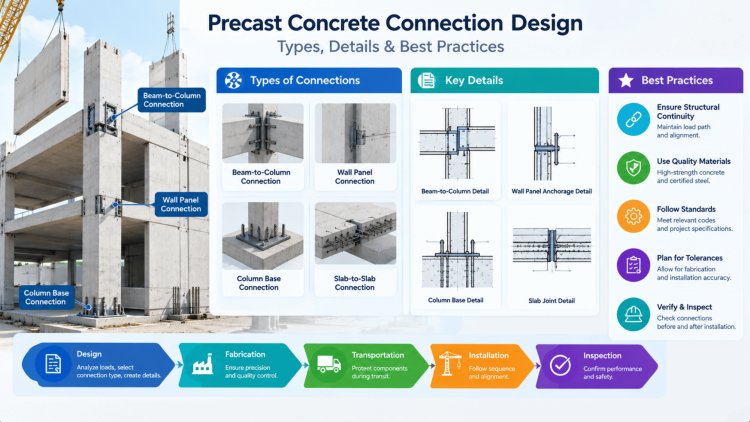
Selecting the appropriate precast connection type is a function of load magnitude, required ductility, production capabilities, erection sequence, and long-term maintenance considerations. Each connection family has distinct structural characteristics, advantages, and limitations that must be carefully weighed in the design process.
Bolted connections use highstrength steel bolts (typically A325 or A490) threading through embedded steel plates, angles, or slotted holes. They are highly adjustable, allow post-erection disassembly, and are well-suited for connections requiring defined rotational behavior. Slotted holes accommodate construction tolerances of ±1 inch or more in the connection plane. Common applications include column base plates, beam-to-corbel connections, and panel-to-panel shear connections.
Field welding connects embedded steel plates or angles cast into adjacent precast elements. Welded connections offer high rigidity and can transfer both shear and moment when properly detailed. However, they require skilled field labor, are sensitive to weather conditions, and create fixed conditions that may induce restraint forces under thermal movement. Weld inspection per AWS D1.1 is mandatory for structural welds. ASTM A36 or A572 Gr. 50 plates are standard.
Grouted connections use nonshrink, high-strength grout (minimum 5,000 psi) to fill the interface between precast elements — including grouted splice sleeves, keyway joints, and bearing pad pocket connections. Grouted sleeve couplers achieve full reinforcing bar continuity in tension and compression and are extensively used in seismic precast moment frames. Proper venting and grout consolidation are critical; cold-weather grouting requires thermal protection protocols per ACI 306.
Mechanical connections encompass proprietary hardware systems including threaded couplers, swaged bar splices, shear keys with mechanical interlock, and post-installed anchor systems. These systems often offer the fastest field installation times and eliminate the curing delays associated with grouted systems. Mechanical connections must be qualified by testing per ICC-ES AC133 or equivalent standards. They are particularly favored in fast-track construction schedules and in retrofit applications.
For high-seismic applications, grouted splice sleeve connections complying with ACI 550.3 provisions have demonstrated superior ductility performance in laboratory testing and are the preferred choice for Special Precast Moment Frames (SPMF).
Precast Connection Types: Bolted, Welded, Grouted & Mechanical
Bolted Connections
Welded Connections
Grouted Connections
Mechanical Connections
Successful precast connection detailing is built on the precise specification of hardware components, a rigorous approach to dimensional tolerances, and a deep understanding of installation accessibility in the field. Even a structurally adequate connection design can fail in practice if the hardware cannot be accessed, set, or inspected by ironworkers and field crews working under real job-site conditions.
Structurally adequate hardware must still be accessible, settable, and inspectable under actual job-site conditions.
Connection Hardware, Tolerances
& Detailing Best PracticesDesign connections for the worst-case tolerance stack—and for real field access.
The benefits of rigorous precast concrete connection design extend far beyond satisfying structural calculations. When connections are engineered with both structural performance and field constructability in mind, projects experience faster erection, improved durability, reduced coordination conflicts, and lower lifecycle costs. Precision at the connection level directly influences every downstream phase of the structure's service life.
Well-detailed connections ensure the actual structural behavior of the completed assembly matches the assumptions used during engineering analysis. Proper embedment lengths, plate dimensions, anchor configurations, weld returns, and reinforcement detailing help eliminate stress concentrations and reduce premature failure risks.
In seismic applications, properly detailed ductile connections allow energy dissipation through controlled yielding rather than brittle fracture, significantly improving structural resilience and life-safety performance.
Connections that account for fabrication tolerances, erection sequencing, crane access, and field adjustment requirements significantly reduce RFIs, installation delays, and change-order exposure. Accurate detailing supports predictable erection workflows and minimizes disruption during construction.
Early collaboration among the Engineer of Record, precast manufacturer, erection contractor, and detailing team creates alignment that delivers measurable schedule improvements and smoother project execution.
Long-term durability depends heavily on connection protection strategies. Exposure conditions should drive the specification of galvanizing, hot-dip coatings, stainless steel components, sealants, and corrosion-resistant details that protect critical hardware throughout the structure's service life.
Accessible inspection points, properly filled grout pockets, and moisture management detailing significantly reduce future maintenance requirements while extending service life performance.
Precision in precast connection detailing is not an enhancement—it is a fundamental requirement for structural reliability, constructability, and lifecycle performance. Every hour invested in connection design, tolerance coordination, embedment review, and erection planning generates dividends throughout fabrication, installation, inspection, maintenance, and long-term operation. Well-engineered connections create buildings that perform as intended, erect efficiently, and remain durable for decades under real-world service conditions.
How Accurate Connection Detailing Improves Performance & Constructability
Structural Performance
Constructability & Schedule
Durability & Maintenance
Key Takeaways for Practicing Engineers
Industry Resources
Final Engineering Perspective
What's Your Reaction?