Precast Concrete Lifting and Handling Design: Avoiding Damage Before Installation
In precast concrete construction, the structural integrity of a panel or element is only as good as the care taken during its journey from the casting bed to final installation. Lifting and handling considerations are not an afterthought — they are a fundamental part of the precast detailing and design process that must be addressed early and coordinated across disciplines. Improper lifting design routinely causes cracking, spalling, anchor pullout, and costly field repairs that delay erection schedules and compromise structural performance. This guide is intended for structural engineers, precast detailers, and erection planners responsible for ensuring that every element — from hollow core slabs and double-tees to architectural cladding panels and structural columns — arrives at the jobsite in the condition it was designed to be in. The following sections address the full lifecycle of a precast element's handling demands: from stripping at the plant through transportation, storage
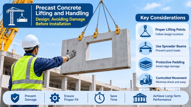
Why Lifting Considerations Must Begin at Detailing
One of the most common and costly mistakes in precast production is treating lifting hardware as a field decision rather than a design decision. By the time an element reaches the casting bed, the reinforcement cage is already placed — and retrofitting lifting insert locations around existing rebar is inefficient at best and structurally compromised at worst.
Lifting and handling must be fully coordinated during the detailing phase, before shop drawings are approved and production begins.
Temporary Load Conditions Often Control Design
The temporary load conditions imposed during stripping, storage, and transportation often govern element design in ways that the final in-service state does not. A slender architectural panel, for example, may experience its maximum tensile bending stress not under wind or seismic load, but the moment it is stripped from the casting bed in a horizontal orientation.
Engineers must evaluate all temporary load cases explicitly, including the effects of pick point geometry, rigging angle, and element self-weight, using applicable provisions from ACI 318, PCI Design Handbook (Chapter 5), and manufacturer-certified anchor design data.
Coordination Creates Opportunities for Cost Reduction
Failure to coordinate early also means missed opportunities to reduce costs. Strategically placed lifting inserts can often be positioned to double as erection bracing anchors or temporary connection points, reducing embedded hardware count and simplifying the erection sequence.
Coordination with the erection engineering team during shop drawing production is therefore not optional — it is a core deliverable of comprehensive precast detailing.
PCI Guidance
PCI MNL-127 (Erector's Manual) and PCI MNL-128 (Plant Quality Control) both mandate that lifting hardware be specified by the Engineer of Record or a qualified precast engineer — not selected arbitrarily at the plant.
Early Coordination Reduces RFIs
Insert locations resolved at detailing eliminate field conflicts and casting-bed rework.
Temporary Load Cases Often Govern
Stripping and transport stresses can exceed service stresses — they must be explicitly calculated.
Multi-Use Hardware Saves Cost
Lift inserts designed to also serve as brace anchors reduce embedded item count and simplify erection.
By the time an element reaches production, lifting strategy should already be fully resolved. Pick points, rigging geometry, temporary load paths, and erection coordination are structural design decisions that belong in detailing, not in the field.
Successful precast projects treat lifting and handling as engineered load cases from day one, ensuring safety, constructability, cost efficiency, and reliable field execution.
The precast industry uses a well-established family of proprietary and custom lifting inserts, each suited to specific element types, load magnitudes, and handling configurations. Selecting the correct anchor system requires understanding both the structural demand and the physical constraints of the element geometry.
Cast-in ferrule inserts accept threaded lifting bolts and are ideal for flat slab elements, architectural panels, and situations requiring flush or recessed hardware after lifting. Coil inserts provide similar function with a helical coil thread that distributes pullout forces over a greater embedment depth. Both types require minimum edge distances and concrete strengths per manufacturer load tables.
Rebar loops bent from deformed bar and cast integrally with the element are economical and highly reliable for large, heavy elements such as double-tees and structural beams. Eye bolt inserts cast into the element top provide similar utility. Both configurations must be designed for the full factored lift load, including dynamic amplification factors (typically 1.2 to 1.5) per PCI recommendations.
Systems such as Halfen, Peikko, and DEHA anchors are engineered inserts with certified load ratings verified by independent testing. They offer precise load capacity documentation, adjustable positioning capability, and compatibility with crane shackles or spreader bar hardware. These systems are particularly common in heavy industrial precast and in architectural elements requiring precise rigging control.
Insert selection cannot be done in isolation from rigging hardware. The angular capacity of an insert — how much the lift line can deviate from vertical before the rated capacity is reduced — must be confirmed against the actual rigging geometry. Most inserts are rated for a maximum of 45° from vertical, with capacity reductions applied at larger angles. Spreader bars are often required to maintain acceptable rigging angles on wide elements. Rigging details should appear on the precast erection drawings and be reviewed by the erection engineer.
All lifting insert capacities must be verified against the factored design lift load, accounting for concrete compressive strength at time of lift (f'ci), edge distance reduction factors, group effect reductions for closely spaced inserts, and concrete breakout capacity per ACI 318 Appendix D (now Chapter 17). Manufacturer load tables are typically based on normal-weight concrete at specified strength — adjustments are required for lightweight concrete mixes, which are common in architectural precast.
Lifting Anchors, Inserts, and Hardware Selection
Ferrule & Coil Inserts
Lifting Loops & Eye Bolts
Proprietary Plate & Channel Anchors
Rigging Hardware Coordination
Capacity Verification
Successful precast handling design requires more than selecting lifting hardware. Every lifting operation depends on accurate center-of-gravity calculations, properly located lift points, and rigorous evaluation of temporary stresses during stripping, storage, transportation, and erection. These temporary conditions frequently govern handling reinforcement requirements and can become the controlling design case for many precast elements.
Every precast element possesses a center of gravity that must be accurately determined in three dimensions before lifting hardware locations are finalized. Symmetrical elements such as rectangular columns and uniform slabs generally have predictable center-of-gravity locations, while complex geometries require detailed analysis.
L-shaped spandrels, haunched beams, façade panels with irregular openings, and members containing large blockouts require center-of-gravity calculations based on actual volume distribution. Modern BIM models provide an efficient method for validating manual calculations and confirming total element weight.
Lift points must be arranged such that the element hangs in its intended orientation without uncontrolled rotation, excessive eccentricity, or instability. Connection hardware placement must always be coordinated with the calculated center of gravity.
Vertically erected components such as wall panels and columns require lift points positioned above the vertical center of gravity. Horizontally erected elements such as beams and slabs generally utilize multiple lift points distributed symmetrically around the center of gravity to limit flexural demands during lifting.
Large panels typically benefit from four-point lifting arrangements that improve load distribution, provide redundancy, and reduce element deflection during handling.
Temporary stresses are often the most critical and most frequently underestimated aspect of precast handling design. Tensile and compressive stresses generated during handling operations must be evaluated independently for each stage of the element's lifecycle. Different support conditions, lifting arrangements, and dynamic effects govern each phase.
Peak handling stresses frequently occur when elements are stripped from casting beds. Concrete strength is at its minimum acceptable level, and bending stresses between lift points and at element overhangs must be verified carefully. Dynamic load factors ranging from 1.2 to 1.5 typically apply.
Dunnage placement controls support reactions during storage. Support locations should align with design assumptions. Improperly positioned dunnage can create unintended cantilever effects and induce cracking in otherwise acceptable elements.
Transportation introduces additional bending caused by vehicle motion, braking forces, vibration, and roadway irregularities. Long-haul delivery conditions require consideration of dynamic amplification and support spacing effects throughout transport.
Rigging geometry, sling angles, rotation effects, eccentric loads, and weak-axis bending must be evaluated. Slender wall panels and vertical members are particularly vulnerable to lateral bending stresses during erection activities.
Temporary tensile stresses in concrete are commonly limited to 7.5√f'ci for uncracked sections during handling. Whenever calculated handling stresses exceed allowable limits, additional crack-control reinforcement, handling reinforcement, modified lift-point configurations, or revised erection procedures should be incorporated into the design.
Handling reinforcement should never be treated as a secondary design consideration. Many successful service-stage elements have experienced damage during handling because temporary load cases were not fully evaluated during engineering.
Most precast handling failures occur before a structure ever reaches service. Accurate center-of-gravity determination, carefully positioned lift points, realistic dynamic load assumptions, and comprehensive temporary stress analysis are essential for safe handling operations. The most successful precast projects treat stripping, storage, transportation, and erection as independent structural load cases that deserve the same engineering rigor as the final design condition.
Locating Lifting Points, Center of Gravity & Temporary Stresses
Center of Gravity Calculation
Lift Point Location Strategy
Temporary Stress Analysis
Critical Handling Stages
Temporary Tensile Stress Control
Engineering Takeaway
Best Practice: All lifting insert locations, types, and capacity data should appear explicitly on the precast shop drawing—not just referenced in a specification. Field personnel should never have to guess where or how to rig an element.
Integrate lifting hardware design into the earliest phases of precast detailing—and maintain rigorous coordination through shop drawing approval and plant production—so the structural performance designed in the office is fully realized in the field.
Reinforcement Coordination,
Detailing, and Safe Erection PracticesElements that arrive crack-free and dimensionally correct eliminate remediation, schedule risk, and liability exposure.
What's Your Reaction?