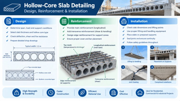
Hollow-Core Slab Detailing: Design, Reinforcement & Installation
Hollow-core precast concrete slabs are among the most widely used structural floor and roof systems in modern construction. Their longitudinal voids reduce self-weight while preserving structural depth, enabling long clear spans with minimal material — a critical advantage in commercial, residential, and industrial applications. Yet realizing these efficiencies in the field depends entirely on the quality and accuracy of the detailing that precedes fabrication. This guide addresses the full lifecycle of hollow-core slab detailing: from understanding prestressing strand layouts and slab geometry, to producing shop drawings that meet production and erection tolerances. Whether you are a structural engineer specifying bearing conditions, a precast detailer preparing production documentation, or a contractor coordinating field installation, the principles covered here provide the technical foundation for reliable, code-compliant work.
Prestressing Strands, Reinforcement Layouts & Slab Geometry
Prestressing Strand Fundamentals
Hollow-core slabs are almost universally manufactured using pretensioned prestressing strands — typically low-relaxation, seven-wire strands conforming to ASTM A416. Common diameters are ½ in. (12.7 mm) and 0.6 in. (15.2 mm), stressed to approximately 75% of their ultimate tensile strength before concrete placement.
The prestress force is transferred to the concrete through bond after the concrete reaches a minimum release strength, typically 3,500 psi.
Strand layout — number, diameter, and vertical position — is determined by the design moment demand, allowable tensile stress limits at release, and long-term camber control requirements. Debonding (blanketing) selected strands near slab ends is a common technique to manage end-zone stresses and reduce top-fiber tension at release.
Slab Dimensions & Void Geometry
Standard hollow-core units are produced in widths of 48 in. (4 ft) and 96 in. (8 ft), with nominal depths ranging from 6 in. to 16 in. or greater for deep-section special products. The void geometry — number of cores, core diameter, and web thickness — is proprietary to each producer's extruder or slip-former configuration.
Design tables published by individual manufacturers or the Precast/Prestressed Concrete Institute (PCI) Design Handbook provide allowable superimposed load vs. span tables for each section.
Critical Shop Drawing Verification Items
Critical dimensional parameters that must be confirmed in shop drawings include: slab depth tolerance (±⅛ in.), width tolerance (–¼ in., +⅜ in.), length tolerance (±½ in. for units up to 30 ft), and camber variability.
Camber differentials between adjacent units — often called "differential camber" — are a leading cause of field complaints and must be addressed in bearing seat and topping design.
Supplemental Reinforcement
While hollow-core units are inherently prestressed, supplemental mild steel may be placed in cores or over the top surface. Core-grouted rebar is used at bearing ends, at openings, and where continuity reinforcement is required.
Designers must confirm that grouting can physically be achieved — cores as small as 5 in. diameter may restrict placement of standard rebar sizes.
Initial Prestress Level
Typical jacking stress as a percentage of strand ultimate tensile strength (fpu) per ASTM A416
Max Standard Depth
Common maximum nominal slab depth for standard extruded hollow-core sections
Length Tolerance
Allowable length tolerance for hollow-core units up to 30 ft, per PCI MNL-116
Min Release Strength
Minimum concrete compressive strength required at strand detensioning for standard production
Successful hollow-core design depends on balancing strand patterns, release stresses, void geometry, tolerances, and long-term camber performance while maintaining constructability during fabrication, transport, and erection.
Prestressing strands provide the strength, slab geometry provides the efficiency, and proper detailing ensures hollow-core units perform reliably from casting bed to completed structure.
Slab openings and bearing conditions are two of the most consequential — and most frequently misdetailed — aspects of hollow-core design. Errors in either category directly affect structural integrity, fire resistance, and erection safety.
Openings in hollow-core slabs must be planned before fabrication. Field-cut openings are a persistent problem in the industry: cutting cores after prestress transfer compromises the structural capacity of the unit and may violate the design basis entirely. All openings — for mechanical penetrations, stairwells, elevator shafts, or structural connections — must be coordinated and shown on shop drawings prior to production.
The structural impact of an opening depends on its position relative to the span direction and its proximity to slab ends. Openings parallel to the span (longitudinal) are generally less critical; openings perpendicular to the span that interrupt one or more strands require design intervention. Accepted methods include: field-placed reinforcing bars in adjacent grouted cores, structural steel headers, or specification of a notched or special unit from the producer. The governing design check is the reduction in shear and flexural capacity of the net section.
Shop drawings must clearly dimension all openings from the slab end and edge, identify cut cores by number, show supplemental reinforcement details, and note the maximum allowable field variation from the dimensioned location — typically ±1 in. for small penetrations.
Adequate bearing length is essential for load transfer and erection safety. The PCI Design Handbook recommends a minimum bearing length of 3 in. on concrete and masonry supports and 4 in. on steel supports, measured from the support face to the nearest void edge. Many structural engineers of record (SER) specify longer bearing for added robustness, particularly in seismic design categories C and above.
End conditions influence both the shear capacity of the unit and the detailing of the diaphragm connection. Common end conditions include:
Unit ends are cut perpendicular to the span. Cores are typically grouted solid for a minimum of 12 in. from the bearing end to provide web shear capacity and allow hardware embedment.
Used where the slab must bear at a reduced depth — common at steel beams with a top flange obstruction. Notching reduces the net shear area and requires explicit design verification by the SER.
Cores at the bearing end are filled with concrete and a headed anchor or rebar is embedded for connection to the support. Detail must match the hardware shown in the structural drawings.
Bearing pad material — elastomeric strip, hard plastic, or sand-cement grout — must be specified and shown on shop drawings. Differential bearing elevations across a bay must be within tolerance to prevent rocking and cracking during erection.
Blocked-Out End Core
Notched / Recessed End
Standard Square End
Openings, Bearing Lengths & End Conditions
Slab Openings: Sizing, Location & Reinforcement
Bearing Length & End Conditions
Square end (standard):
Notched/recessed end:
Blocked-out end cores:
Hollow-core slabs must function as part of the building’s lateral force-resisting system diaphragm. In most structures, this means transferring in-plane shear and chord forces from the slab field to perimeter beams, shear walls, or moment frames. The mechanism for this transfer is the combination of grouted keyway joints between adjacent units and mechanical connections at slab edges and ends.
Rigorous review, BIM coordination, and PE-stamped documentation prevent diaphragm discontinuities and field-generated substitutions.
Diaphragm Connections, Structural
Interfaces & Shop Drawing DocumentationShop drawings must support manufacture, marking, storage, shipping, and erection—without referring back to other drawing sets.
Hollow-core slab detailing demands a precise, coordinated effort across structural design, precast production, and field erection. The following principles summarize the critical practice standards covered in this guide.
Engage the precast producer early in design to confirm the specific section properties, strand patterns, and dimensional standards of their extruder or slip-former. Generic section properties from tables are a starting point — final design must be reconciled with the actual product.
Every penetration — no matter how small — must appear on coordinated shop drawings reviewed and approved before production begins.
BIM coordination with MEP trades before shop drawing issuance is the most effective prevention mechanism available, and is now considered standard practice on projects of any significant scale.
Bearing length design must account for these tolerances cumulatively — not just the nominal dimension:
Use the PCI tolerance tables in MNL-116 as the starting point, and verify that the specified minimum bearing length is achievable in the worst-case tolerance stack condition before approving shop drawings.
Three distinct operations, each with different material and placement requirements:
Each must be fully specified on the shop drawings and in the project specifications — including minimum compressive strength, flowability requirement, grouting sequence, and curing.
The structural engineer of record must perform a substantive technical review — not a cursory stamp — of all hollow-core shop drawings. The review should:
Thorough detailing is not overhead — it is the single most cost-effective investment in a precast project, preventing RFIs, field corrections, and schedule delays that far exceed the cost of additional engineering hours at the front end.
Key Takeaways & Professional Resources
Design to Producer Geometry Early
Coordinate All Openings Before Production
Detail Bearings for Tolerance, Not Nominal
Specify Grouting Completely
Require SER Review of All Shop Drawings
Industry Standards & References
BIM & Digital Workflow Tools
What's Your Reaction?