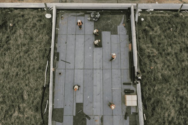
Roof Deck Detailing for Canopy Structures
Canopy roofs occupy a unique and demanding space in structural steel design — exposed to weather, subjected to unbalanced loads, and often featured as architectural statements. Unlike conventional enclosed roof systems, canopy decks demand a more rigorous approach to detailing: every edge condition, support connection, and fastener pattern must account for the absence of a protecting enclosure above and the full fury of environmental loading below. This guide is written for structural detailers and BIM technicians who are already comfortable with standard metal deck systems and need focused, constructible guidance specific to canopy applications — from selecting the right deck profile and gauge to detailing the critical perimeter conditions that keep panels secure under uplift and lateral forces.
What Makes Canopy Deck Detailing Different
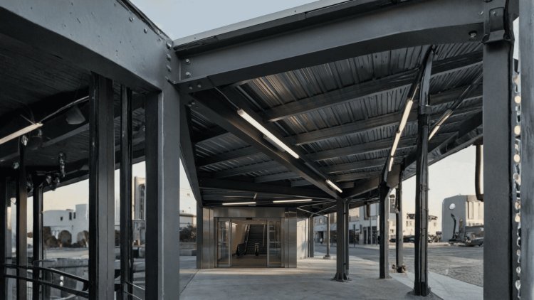
A canopy is not simply a roof without walls. It is an independent structural system exposed directly to wind, temperature variation, precipitation, and visual scrutiny. Unlike enclosed buildings, canopy decks receive no assistance from conditioned building envelopes, enclosed air pressure effects, or concealed finishes. As a result, structural detailing requirements become more demanding and often governed by uplift, appearance, movement, and perimeter behavior rather than gravity loads alone.
Canopies Behave Like Exposed Structural Machines
Every connection, fastener, closure, weld, and alignment detail remains exposed to both environmental loading and public view, making canopy detailing simultaneously a structural and architectural discipline.
Shared Protection
• Interior load sharing
• Concealed fasteners
• Limited temperature exposure
• Reduced visual sensitivity
Fully Exposed
• Visible underside
• Thermal movement exposure
• Exposed perimeter forces
• Higher detailing requirements
Wind Uplift Often Controls Everything
Requirements Unique to Canopy Systems
Profile depth, thickness, coating, span, uplift, connections, edge geometry, and exposure must be selected as one system before perimeter details are finalized.
Common choice for moderate canopy spans
Wide-rib deck is often suitable where spans, gravity loads, uplift, and support spacing fit the manufacturer’s tables. Its shallower profile generally simplifies perimeter closures and flashing compared with deep-rib systems.
Candidate for longer spans and exposed structure
Deep-rib deck can increase stiffness and span potential where intermediate joists are undesirable, but it changes every edge condition around the canopy.
May be adequate for lower-intensity uplift and shorter spans, but thin-gage connection pull-through and local failure must be checked explicitly.
Often a practical middle choice for stronger span and uplift performance, subject to the actual load combination and connection design.
May be appropriate for higher uplift, longer spans, edge or corner zones, or demanding connection requirements.
A common minimum coating designation for exposed or exterior steel deck where the specification and environment support it.
Provides a higher specified zinc coating weight than G90; confirm availability, forming, cut-edge, and finish requirements.
Aluminum-zinc systems may suit selected environments, but compatibility, edge treatment, contact metals, and fire or warranty requirements must be checked.
Changing deck depth or gauge after detailing can alter much more than the panel itself.
Select profile, gauge, finish, and connections as one verified system. Use Type B when the span and loading fit its tables; consider Type N when longer spans justify the added edge complexity; and let the actual uplift, corrosion exposure, bearing, and manufacturer data—not rules of thumb—control the final specification.
Deck Profile and Gauge: Select for the Actual Canopy
1.5-Inch Wide Rib
3-Inch Deep Rib
Profile Selection Matrix
Criterion
1.5″ Type B
3″ Type N
Typical use
Moderate spans and conventional canopy framing
Longer spans or exposed structure
Edge detail
Generally simpler
Closures and flashing must accommodate deep ribs
Support spacing
May require more frequent supports at long spans
May permit wider support spacing if tables allow
Connection risk
Check thin-gage pull-through and uplift
Check profile-specific fastener and edge behavior
Aesthetic impact
Shallower exposed rib
Deeper exposed rib and stronger visual expression
Decision control
Manufacturer span, load, and uplift tables
Manufacturer span, load, uplift, and closure data
Gauge Selection Under Uplift
22 Gauge
20 Gauge
18 Gauge
Finish and Corrosion Selection
Baseline Galvanized
Heavier Zinc Coating
Alternative Coatings
Canopy Deck Selection Checklist
Profile Changes Are Not Local Changes
The Canopy Principle
In canopy detailing, perimeter and support connections are where uplift forces concentrate, water infiltration originates, and inspectors focus their attention. Proper detailing ensures design intent is captured and structural performance maintained.
Puddle welds through the deck to supporting flanges are standard. For canopy edges, weld every flute at edge/corner zones, transitioning to every other flute in field zones. Use weld washers for 22 ga. or thinner decks. Specify minimum 5/8" diameter weld with 3/16" throat. Show symbology clearly, distinguishing edge vs. field patterns.
Continuous perimeter angles (L3×3×1/4" or L4×4×5/16") close open ribs, provide flashing nailers, and transfer diaphragm shear. Detail stitch welds at 12" o.c. to beams, plus self-drilling screws at 6" o.c. through deck webs. Do not rely solely on puddle welds — perimeter angles must provide independent uplift load paths.
Open-rib decks allow rain, insects, and birds entry. Use closed-cell foam strips at panel ends, compressed and sealed before perimeter angle installation. For 3" deep-rib decks, steel closure plates are preferred for rigidity and durability. Show closure details in section at gutters, free edges, and column bearings.
Cantilevered canopy tips place panels in negative bending with full uplift. Detail continuous HSS or W-shape edge beams welded to deck ribs with cover plates or angles. Limit cantilever deflection to L/240 under combined load. Flag orientation clearly in notes to prevent backward panel installation errors.
Perimeter and support connections are critical canopy details. Explicit weld patterns, perimeter angles, closure strips, and cantilever reinforcements ensure uplift resistance, water protection, and diaphragm continuity — reducing inspection issues and field errors.
Perimeter, Edge & Support Conditions
Deck-to-Supporting Steel (Structural Welds)
Perimeter Angle (Edge Member) Detailing
Flute Closure Strips
Cantilevered Deck End Conditions
Key Insight
Canopy deck systems must be evaluated as complete structural systems rather than isolated deck panels. Beyond individual connections and fasteners, engineers and detailers must verify diaphragm behavior, lateral load transfer, drainage performance, thermal movement accommodation, and interdisciplinary BIM coordination. Successful canopy projects depend on understanding how structural, architectural, roofing, and MEP components interact around the deck perimeter.
Every deck panel, fastener pattern, chord member, collector connection, drainage component, and perimeter detail contributes to overall canopy performance.
Canopies supported by moment frames, braced frames, or building attachments rely on the roof deck diaphragm to transfer lateral forces efficiently. Unlike conventional building roofs, canopy diaphragms often have irregular boundaries and limited chord development.
Confirm that deck gauge, profile depth, fastener spacing, side-lap attachment pattern, and diaphragm geometry satisfy required shear strength and stiffness. Reference the applicable SDI diaphragm design tables directly on the detail sheet to simplify review and fabrication coordination.
Structural camber and roof slope frequently work against each other, creating localized ponding areas that are not apparent in traditional plan views.
Verify camber, roof slope, scupper elevations, and gutter elevations directly within the BIM model before issuing fabrication drawings.
Model panels individually for accurate clash detection, material takeoffs, lap verification, and opening coordination.
Assign field, edge, and corner fastener zones as model parameters to automate annotation and eliminate plan discrepancies.
Include perimeter angles, closure members, and edge reinforcement explicitly instead of leaving them to fabrication assumptions.
Create dedicated color-coded fastener zone plans that become the source of structural deck documentation.
The highest concentration of structural forces, drainage components, roofing interfaces, fascia systems, fastener density, and clash risks occurs at the canopy boundary. Successful detailing focuses disproportionate attention on this zone.
Successful canopy deck projects require more than compliant structural calculations. Diaphragm force paths must be explicit, drainage geometry must be verified, perimeter conditions must be modeled accurately, and BIM coordination must include roofing, structural steel, gutters, fascia systems, and MEP interfaces. When these systems are coordinated before fabrication, projects achieve cleaner installation, better drainage performance, fewer RFIs, and significantly greater long-term durability.
Diaphragm Action, Drainage & BIM Coordination
A Canopy Deck Is Both Structure and Diaphragm
Diaphragm Design for Lateral Load Transfer
Chord Members
• Do not rely on perimeter beams
• Show weld/screw spacing
• Verify continuous force pathCollector Members
• Distinct deck attachments
• Transfer to frames/braces
• Clearly identified on detailsDocument SDI Design Inputs Explicitly
Opposing Camber
Coordinated Geometry
Model the Canopy as It Will Be Built
Individual Deck Panels
Zone-Based Properties
Model Perimeter Angles
Shared Coordination Views
Canopy Coordination Workflow
Most Canopy Problems Occur at the Perimeter
Coordination Is the Final Structural Detail
Canopy deck detailing is governed by exposure, uplift, edge behavior, drainage, diaphragm transfer, and constructability. Treat every perimeter condition as a designed system—not as a variation of enclosed-roof practice.
Select profile and gauge using project-specific gravity and wind uplift demands for field, edge, and corner zones.
Show separate support, perimeter, and sidelap fastening patterns for each canopy pressure zone.
A free edge, gutter end, column bearing, scupper, and cantilever tip are separate structural and waterproofing conditions.
Use the calculated field-zone uplift, gravity demand, support spacing, and diaphragm pattern. Confirm that the standard pattern remains valid at changes in span or support condition.
Check increased uplift, edge angles, closure attachment, perimeter chord transfer, and access for welds or screws.
Verify the highest applicable pressure, connection resistance, local reinforcement, and any special fastener or washer requirements.
Show edge angle, closure, attachment, uplift restraint, and chord connection.
Coordinate gutter support, water path, closure, trim, and corrosion protection.
Verify local support, deck bearing, column connection, and any discontinuity at the support.
Check free-edge stiffness, uplift, vibration, fascia, closure, and actual cantilever capacity.
Explicitly identify chord members; do not assume the perimeter beam automatically performs every chord function.
Show how diaphragm forces reach the lateral-force-resisting system through capacity-designed connections.
Check partial panels adjacent to chords, collectors, and reaction members; special evaluation or added connections may be required. [801]
Verify sidelap spacing for required diaphragm stiffness, not only minimum construction fastening.
Confirm structural camber and deck drainage slope do not oppose one another.
Verify primary and overflow scupper sizing, elevations, discharge, and wall penetrations.
Do not apply a 200-foot expansion-joint rule without verifying the roof system, manufacturer, movement criteria, and project specification.
Embed zone, profile, gauge, fastener, and edge-condition parameters in panel objects and export them with the model.
Exposed edges and uplift zones make canopy work fundamentally different from enclosed roof work.
Design the canopy from the perimeter inward: quantify uplift by zone, select the profile and gauge, detail every edge, connect the diaphragm explicitly, verify drainage, and make the BIM model carry the same information as the drawings. Rigor at the perimeter is what makes the entire canopy reliable.
Key Takeaways and Detailing Checklist
Confirm Against Actual Uplift
Use Zone-Specific Schedules
Detail Every Unique Edge
Zone-Specific Fastener Review
Interior Zone
Perimeter Zone
Corner Zone
Perimeter and Cantilever Details
Diaphragm Chords and Collectors
Drainage and BIM Coordination
Final Canopy Release Checklist
Do Not Issue a Generic Canopy Detail
The Canopy Principle
What's Your Reaction?