Light Gauge Steel Foundation Connections: Anchor Bolts, Base Tracks & Load Transfer
The interface between cold-formed steel (CFS) wall framing and a concrete or masonry foundation is one of the most structurally critical — and most frequently misdetailed — zones in any light gauge steel building system. Proper LGS-to-foundation connections must simultaneously resist gravity loads, lateral shear, and uplift forces, while accommodating the dimensional tolerances inherent in cast-in-place concrete. When these connections are designed and installed correctly, they create a continuous, reliable load path from the roof diaphragm all the way down to the footing. When they are not, the consequences range from serviceable nuisances like racking and air infiltration to life-safety failures under wind or seismic events.
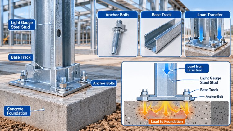
LGS-to-Foundation Interfaces & Base Track Detailing
Understanding the LGS-to-Foundation Interface
The LGS-to-foundation interface is where structural continuity begins. At this junction, the cold-formed steel wall system must transfer all applied loads — axial compression from gravity, shear from wind or seismic lateral forces, and tension from uplift — into the concrete or masonry substrate below.
The interface is not a single component but rather an assembly: the base track (or bottom plate), the anchor bolts or powder-actuated fasteners, any sill gasket or moisture barrier, and the concrete substrate itself.
Designers must account for the fact that concrete foundations are inherently imperfect surfaces. Variations in elevation, surface texture, and embedded hardware alignment all affect how well the CFS system bears on and connects to the foundation. Coordination between the structural engineer of record, the CFS detailer, and the concrete subcontractor is essential from the earliest stages of a project. Embedding anchor bolts or installing cast-in hardware after the fact creates compounding tolerances that are difficult to manage in the field.
Base Track and Bottom Plate Detailing
The base track is the lowest horizontal member of a CFS wall assembly and serves as the primary interface element. It is typically a U-shaped channel — matching the stud width — into which the bottom of each wall stud is inserted and fastened.
Base track thickness should be selected to match or exceed the stud thickness, as it must transfer concentrated bearing loads at stud locations and distributed shear along its length.
Key detailing considerations include: track gauge selection (minimum 54-mil / 16-gauge is recommended for load-bearing applications, with heavier gauges for high shear walls), slot or oversized holes for anchor bolts to accommodate concrete placement tolerances, and sill gaskets to provide a capillary break and air seal between the steel and concrete. Where the wall sits on a wood sill plate (a hybrid condition), the base track must be fastened to both the sill plate and the concrete per the engineer's specification.
Successful LGS foundation connections depend on more than anchor spacing alone. Track gauge, bearing conditions, moisture protection, load path continuity, construction tolerances, and field adjustability must all be coordinated to achieve a durable and structurally reliable system.
Every load carried by a light gauge steel structure ultimately passes through the base track and into the foundation. Accurate detailing at this interface is essential for structural performance, constructability, moisture control, and long-term building durability.
Anchor bolts and hold-down hardware form the mechanical heart of any LGS foundation connection. Selecting the right system — and installing it correctly — is fundamental to achieving the engineered load path. For comprehensive specifications and product data relevant to CFS structural systems, engineers and contractors can reference technical resources available through Consac.com.
Cast-in-place (CIP) anchor bolts — typically ASTM F1554 Grade 36 or Grade 55 — are the preferred option for new construction. They are set in the concrete form before the pour, providing the highest pullout resistance and best load transfer efficiency. Standard diameters range from 1/2" to 1" with embedment depths of 7" to 15" depending on design loads. Spacing is engineer-specified but typically falls between 24" and 48" o.c. for shear walls, with closer spacing (6"–12") at high-uplift chord locations. Proper template use during placement is critical — misaligned bolts that fall outside base track hole tolerances create expensive field remediation scenarios.
When CIP bolts are missed or mislocated, post-installed anchors — either mechanical expansion anchors (ICC-ES listed) or adhesive/epoxy anchors — provide a code-compliant remediation path. Adhesive anchors (HIT-RE 500, SET-XP, etc.) are generally preferred for CFS applications due to their high tension capacity and suitability for uncracked and cracked concrete. All post-installed anchors must be installed per the ICC-ES Evaluation Report requirements, including hole diameter, cleaning protocol, and minimum embedment. Edge distances and spacing requirements must be verified against ACI 318 Appendix D (or ACI 318-19 Chapter 17) limits, which frequently govern in narrow stem wall or slab-edge conditions.
Hold-down (tie-down) devices resist the net uplift forces that develop at the end studs (chord studs) of shear walls under lateral loading. In CFS construction, hold-downs are typically strap-type or hardware-type (bracket) devices that connect the chord stud assembly to either a cast-in rod, a post-installed threaded rod, or a continuous rod system running through multiple floors. The hold-down must be sized for the design uplift force with a code-required safety factor, and the connection to the stud — through screws, bolts, or welds — must also be verified. Continuous rod systems (CRS) using all-thread rod with bearing plates and compression posts provide an efficient solution for multi-story CFS structures where cumulative uplift loads are significant.
For non-structural or lightly loaded interior partitions bearing on concrete slabs, powder-actuated fasteners (PAFs) through the base track web offer a rapid, cost-effective alternative to anchor bolts. PAFs are not acceptable as the sole fastener for load-bearing or lateral force-resisting walls without specific engineering justification and testing data. When used, fastener spacing, concrete substrate strength (minimum f'c = 3,000 psi), and minimum edge distance from slab edges must all be verified. Many engineers specify PAFs at 24" o.c. max for partition tracks as a standard of practice.
Anchor Bolt Systems, Hold-Downs & Uplift Resistance
Cast-In-Place Anchor Bolts
Post-Installed Anchors
Hold-Down Systems & Uplift Resistance
Anchor Bolt Spacing & Embedment Quick Reference
Condition
Typical Spacing
Min. Embedment
Standard loadbearing wall
48" o.c.
7"
Shear wall (moderate)
24"–32" o.c.
10"
Shear wall (high seismic/wind)
6"–16" o.c.
12"–15"
Chord stud hold-down
At each end stud
12"+ (rod)
Powder-Actuated Fasteners (PAF)
Load transfer in a CFS wall system is a multi-step process that begins at the roof or floor diaphragm and terminates at the foundation. Understanding this sequence is essential for designing and detailing connections that maintain a complete, uninterrupted load path—a fundamental requirement of the International Building Code (IBC) and AISI S100/S400 standards.
Maintain a continuous gravity, shear, and uplift load path from diaphragm to foundation—and manage concrete tolerances through templates, surveys, and engineer-approved remediation.
Load Transfer, Foundation Tolerances
& Installation CoordinationCoordinate the foundation before the framing mobilizes.
Many of the most expensive and difficult-to-correct issues in Cold-Formed Steel (CFS) construction originate at the foundation connection. The interface between the concrete foundation and light-gauge steel framing is responsible for transferring gravity, lateral, uplift, and seismic loads into the structural system. Eliminating common detailing mistakes at this location dramatically improves constructability, durability, and long-term performance.
Base tracks detailed with standard round holes leave little tolerance for anchor-bolt placement variation. Minor field deviations often lead to cutting oversized holes, reducing bearing capacity and creating fit-up problems.
Direct contact between steel framing and concrete creates pathways for moisture migration, condensation, corrosion, and thermal bridging.
Shear wall hold-down forces are frequently concentrated at chord studs. Single studs often lack the capacity required for high-wind and seismic demand conditions.
Relying solely on clamping force from anchor bolts for lateral load transfer can be unconservative, especially under dynamic, seismic, or cyclic loading conditions.
Anchor bolts positioned directly beneath stud webs create installation conflicts, often requiring field modifications that compromise detailing quality.
Light-gauge steel foundation connections should never be viewed as isolated hardware components. The base track, anchor bolts, hold-down assemblies, concrete substrate, moisture barriers, and structural load path function as a single coordinated system. The most successful projects invest heavily in upfront detailing, pre-pour coordination, and constructability reviews because foundation connection mistakes are among the most expensive and disruptive issues to correct after construction begins.
Common Foundation Connection Detailing Mistakes & Best Practices
❌ No Slotted Holes in Base Track
❌ Omitting the Sill Gasket
❌ Inadequate Chord Stud Assemblies
❌ Assuming Friction Transfers All Shear
❌ Poor Anchor Bolt Coordination
Foundation Connection System Coordination
Foundation Detailing Best Practices
Key Takeaway
What's Your Reaction?