How to Reduce Deck Sheet Cutting Through Better Layout
A smarter approach to steel deck layout planning — from grid alignment to BOMbacked workflows — that minimizes field cuts, reduces material waste, and keeps your project on schedule and on budget.
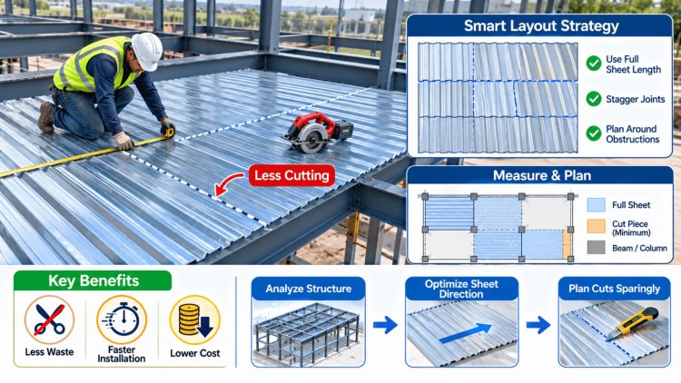
Cut Waste Starts Before You Cut
Most material waste on steel deck projects isn't created at the saw — it's created at the drafting stage. The decisions made during layout planning have a cascading effect on joist and beam span economics, diaphragm performance, and overall material efficiency. When deck runs parallel versus perpendicular to framing, the number of cut conditions, lap conditions, and edge closures changes dramatically.
The core objective is straightforward: reduce the number of unique cut conditions generated by poor alignment, inconsistent sheet directions, and unanticipated field conditions. Every unique cut condition adds labor time, generates scrap, and introduces potential for error at the installation stage.
Direction Matters
Running deck parallel vs. perpendicular to framing directly affects how sheets lap, bear, and terminate. Layout direction should be established first, before beam, joist, opening, and edge closure details are finalized. Good orientation decisions reduce field cuts, simplify installation sequencing, and improve material yield across the entire floor area.
Span Economics
Poor layout forces shorter spans, more intermediate supports, and additional material handling. Direction-aware layout maximizes sheet utilization across full structural bays, reducing scrap generation and minimizing offcuts. The most efficient deck layouts are designed around standard sheet lengths wherever possible.
Diaphragm Performance
Inconsistent sheet orientation disrupts diaphragm continuity and complicates attachment patterns. Proper layout ensures that sidelaps, support attachments, and connection spacing work together to transfer lateral forces exactly as intended by the structural design.
Why Layout Planning Matters
Every sheet direction decision influences labor productivity, diaphragm continuity, sheet utilization, and installation speed. A poor layout multiplies waste through additional cuts, excess closures, unnecessary laps, and field modifications.
Conversely, a coordinated deck plan allows installers to work bay-to-bay with fewer adjustments, fewer measurements, and significantly less scrap generation.
The best time to eliminate a cut is during layout — not during installation. Every field cut that wasn't planned is a signal that something upstream was missed.
Material optimization begins long before fabrication. When deck direction, span strategy, diaphragm requirements, and framing geometry are coordinated during design, waste decreases, installation accelerates, and project costs remain under control.
Accurate layout begins with a disciplined verification process tied directly to the governing structural drawing set. Assumptions about elevations, bearing conditions, and grid alignment are among the most common sources of unplanned field cuts. A thorough pre-layout review eliminates these variables before they reach the job site.
Start with the governing structural drawing set and confirm the revision level and issue date for full traceability. Working from superseded drawings is one of the leading causes of rework and unnecessary recutting on deck projects. Cross-reference all addenda and supplemental specifications before proceeding.
Compile Top-of-Steel (TOS) data for all framing members within the deck zone. Validate that joist seat depths match the intended bearing elevation at every support condition. Even minor discrepancies — as small as 1/8" — can create cumulative misalignment that forces corrective cuts across multiple sheets.
Check all bearing elevations, including edge conditions and wall bearing details, before layout begins. Edge and wall bearing conditions are particularly vulnerable to "field fix" cuts when they aren't resolved at the drawing stage. Confirm minimum bearing lengths are achievable with the planned sheet layout and that closures are accounted for in the BOM.
Overlay the deck layout grid on the structural framing plan and confirm that sheet ends align with framing centerlines or bearing zones. Where openings, penetrations, or framing offsets interrupt the grid, plan the cut conditions explicitly rather than leaving them to field interpretation. Document all deviations from a standard grid as discrete cut notes on the erection drawing.
For further reference on Steel Deck Shop Drawings best practices, confirming elevation data against shop drawing submittals is a critical cross-check before any layout is finalized.
Layout That's Aligned, Not Assumed
Step 1: Drawing Set Verification
Step 2: Elevation Benchmarks
Step 3: Bearing Condition Review
Step 4: Grid Alignment Confirmation
A well-executed steel deck detailing workflow isn’t just about producing drawings—it’s about creating a closed-loop system where every layout decision is reflected in the bill of materials, the erection drawing, and the shop drawing simultaneously. When these outputs are generated in isolation, cutting allowances and overlaps get discovered late—usually in the field, at the worst possible moment.
A closed-loop steel deck workflow prevents late cutting allowances, lap conflicts, and field re-orders by synchronizing layout decisions across every output.
Explore more insights on how detailing workflows reduce errors in the Deck Design resource library, which covers the full spectrum of deck detailing best practices from layout through submission.
Turn the Drawing into a
BOM-Correct WorkflowMake the drawing, erection plan, and BOM agree before fabrication.
Regardless of how refined the upstream workflow may be, every steel deck project requires a formal pre-submission quality gate before fabrication drawings and bills of material are released. This review stage transforms deck cutting from a reactive field activity into a predictable, engineered outcome by eliminating coordination gaps, documentation inconsistencies, and constructability risks before materials reach the jobsite.
Validate that deck profiles, gauges, and material specifications remain consistent throughout all project zones and align fully with structural design requirements. Inconsistent deck types frequently create unexpected bearing, overlap, and connection conflicts that generate avoidable field cutting.
Early profile verification prevents incompatible deck transitions and maintains continuity across the entire floor system.
Review every support condition including interior supports, perimeter framing, wall bearings, edge conditions, and transition zones. Confirm minimum bearing requirements are satisfied without dependence on field-modified sheet ends.
Complete support auditing eliminates many of the fit-up problems commonly discovered during deck installation.
Verify that fastening schedules, weld requirements, puddle weld patterns, side-lap connections, and attachment details are specified throughout every area of the project.
Missing attachment information frequently causes installer uncertainty, site delays, redesign efforts, and costly rework that often results in unnecessary deck modifications.
Resolve deck-edge transitions, slab edge conditions, framed openings, roof penetrations, and conflicts with MEP systems before issuing fabrication documentation.
Uncoordinated openings inevitably become field cuts, increasing installation time while reducing dimensional accuracy and predictability.
Reducing steel deck cutting is fundamentally a coordination and documentation discipline rather than a field installation skill. The most successful projects achieve predictable outcomes by validating structural grids, confirming elevations, coordinating openings, selecting deck directions deliberately, and maintaining complete alignment between detailing documents and fabrication data. When these controls are applied consistently, field cutting becomes a planned exception rather than a routine necessity. Contact Our website for more details.
The Final Quality Gate: Where Cutting Becomes Predictable
Deck Profile & Gauge Verification
Support Condition Audit
Attachment Omission Check
Edge, Opening & Coordination Clash Review
Pre-Submission Quality Gate Workflow
Best Practices for Cut Reduction
Final Quality Principle
What's Your Reaction?