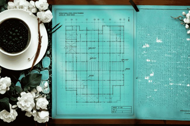
Composite Deck Layouts for Parking Structure Support Areas
A technical deep-dive into deck panel orientation, connection detailing, and structural coordination specific to parking garage support zones — the transfer bays, ramp transitions, and column-line fringe areas where standard layout rules break down.

Why Support Areas Demand a Separate Layout Strategy
Parking structures create some of the most complicated deck-framing environments in commercial construction. Unlike office buildings or warehouses where deck panels typically follow repetitive framing patterns, parking garages introduce ramps, transfer beams, shear walls, expansion joints, vehicle loading concentrations, and irregular geometry that force detailers to develop highly customized support-zone layouts.
What Makes These Zones Different?
Support areas typically occur at column lines, transfer beams, ramp bearing points, and shear wall intersections. At each location the deck must simultaneously satisfy diaphragm requirements, bearing conditions, deck span orientation, closure geometry, and fastening criteria, often within extremely tight framing dimensions.
Critical Support Zone Locations
Supplemental Layouts Are Essential
Standard deck layout drawings rarely provide enough information for parking structure support zones. Supplemental framing plans should explicitly identify deck panel breaks, side-lap fastening patterns, closure details, bearing configurations, weld density adjustments, and support-specific connection requirements.
The Compounding Variables
Varying Bay Widths
Ramp transitions often force panel cuts that disrupt flute alignment and break the standard 3-foot deck module from bay to bay.
Sloped Framing
Ramp geometry changes beam bearing conditions and may require verification of effective flange width and support capacity.
Transfer Structures
Transfer beams crossing perpendicular to deck span create secondary support conditions that require independent end-bearing checks.
Concentrated Vehicle Loads
Wheel loads and barrier impacts generate localized force concentrations that may require additional welds or reinforcing plates.
Localized Changes Create Global Impacts
Wheel Loads
Repetitive concentrated loading drives support detailing requirements.
Barrier Posts
Embedded barriers introduce localized reaction forces.
Supplemental Welds
Added weld density may be required near concentrated loads.
Expansion Joints Must Follow Panel Ends
Expansion joints should align with deck panel termination conditions rather than occur at mid-span. Proper coordination prevents progressive tearing, reduces deck distress, and simplifies long-term maintenance of movement assemblies within parking structures.
Support Zone Detailing Checklist
Support Areas Require Dedicated Detailing, Not Standard Layouts
Parking garage support zones combine irregular geometry, concentrated vehicle loading, ramp transitions, transfer framing, diaphragm requirements, and movement joints into some of the most demanding detailing conditions in steel deck construction. Successful projects depend on supplemental support-zone layouts that explicitly resolve panel placement, fastening patterns, bearing conditions, expansion-joint coordination, and localized reinforcement requirements before construction begins.
In parking-structure composite deck layouts, span direction establishes the primary load path. At column lines, intersecting girders, spandrels, transfer members, and secondary framing can make the otherwise simple span decision much more complex.
Panels run parallel to the main girder and typically bear on regularly spaced secondary framing. This can simplify composite stud coordination along predictable beam flanges.
Where two girders intersect at a column-line corner, one deck orientation rarely resolves both members cleanly. A dominant span direction should be selected and the crossing girder treated as an intermediate support.
Support-area detailing becomes especially important when panel ends are cut around column lines, girder intersections, narrow flanges, or irregular framing. Bearing should be checked at the actual geometry of each panel cut rather than assumed from a typical bay.
Parking-structure column lines frequently contain the very conditions that break a standard deck layout: intersecting girders, narrow support flanges, transfer framing, panel cuts, and local slab-edge requirements. These locations deserve explicit review even when the surrounding bays are repetitive.
Deck Panel Orientation: Span Direction Decisions at Column Lines
Parallel-to-Girder Orientation
Biaxial Framing Intersections
Verify Bearing at Every Panel Cut
Four Checks Before the Detail Is Released
At flat-to-slope transitions, deck panels terminate with pour stops at beam flanges. Both flat and sloped deck terminations must bear simultaneously on the flange, often requiring wider flanges or supplemental bent plates. Ramp slope breaks also introduce horizontal thrust forces that must be resolved through beam connections and verified against weak-axis bending capacity.
Transfer bays with misaligned columns require heavy girders and unique deck layouts. Wide spans (20–30 ft) may exceed standard deck capacity. Solutions include: adding intermediate beams, upgrading to heavier deck profiles, or increasing topping thickness. Deck layout must also account for girder deflection, which can exceed 1″ under load and affect drainage slopes and perimeter connections.
At perimeters, deck must bear on spandrel beams with adequate edge distance for welds. Slab edges require reinforcement to resist lateral forces from vehicle impacts on barrier systems. Where columns interrupt spandrel lines, haunches or brackets must be detailed to maintain continuous deck bearing. Cantilevered deck over columns is acceptable only for short overhangs and must be verified for negative moment capacity.
Ramp transitions and transfer bays demand project-specific detailing rather than typical standards. Coordinating slope geometry, girder deflection, and spandrel reinforcement ensures safe, durable, and efficient parking deck performance.
Connection Detailing at Ramp Transitions & Transfer Bays
Ramp Slope Transitions
Transfer Bay Deck Layouts
Edge and Spandrel Conditions
Key Insight
In parking structures, composite deck serves two vital functions simultaneously. It supports gravity loads through composite slab action while also functioning as a lateral-force diaphragm that transfers wind and seismic forces to the building's lateral system. Support zones introduce abrupt geometric changes, panel terminations, collector locations, and concentrated diaphragm demands, making diaphragm continuity one of the most critical and frequently under-detailed aspects of deck design.
Composite deck must safely carry gravity loads while simultaneously transmitting diaphragm shear forces across the structure. Support zones are where these two responsibilities often collide.
Composite deck works with the concrete slab and supporting beams to carry vehicle loads, superimposed dead loads, and live loads throughout the structure.
The deck diaphragm transfers wind and seismic forces through collectors and drag struts into shear walls, braced frames, or moment frames.
Side-lap fasteners connect adjacent deck panels into a continuous structural diaphragm. While standard field areas may permit relatively wide spacing, support zones near collectors, shear walls, and moment frames frequently require much tighter spacing because diaphragm force transfer reaches peak demand at these locations.
Puddle welds transfer diaphragm forces into supporting beams. Support zones frequently require upgraded weld patterns compared with standard field areas and must be clearly identified on the deck layout rather than left to installer interpretation.
Collector beams gather diaphragm forces from the deck and deliver them directly to the lateral-force-resisting system. In parking structures, collector members often carry heavy gravity loads at the same time, creating a dual-demand condition that requires close coordination between engineering and detailing teams.
Diaphragm Continuity and Fastener Patterns in Support Zones
One Deck. Two Structural Responsibilities.
Gravity System
Lateral System
Side-Lap Fastener Requirements
Why Fastener Zones Matter
Panel-to-Support Weld Patterns
Collector and Drag Strut Coordination
Support-area deck layouts contain more non-typical conditions than standard bays. Use this checklist to systematically review bearing, connections, diaphragm continuity, and documentation before the deck package reaches fabrication or field installation.
Parking-structure support areas should never be treated as minor variations of the typical bay. Bearing geometry, fastener zones, stud coordination, diaphragm continuity, closures, field-verification points, and MEP interfaces all need explicit review. The strongest deck packages convert those conditions into clearly located details and schedules before the deck reaches the site.
Practical Detailing Checklist for Support Areas
Geometry & Bearing
Diaphragm & Lateral
Documentation
What's Your Reaction?