Temporary Bracing in Precast Construction: Detailing for Stability During Erection
In precast concrete construction, the interval between setting a panel and achieving its permanent connection is among the most structurally vulnerable phases of any project. Temporary bracing systems are the critical engineering safeguard that ensures precast wall panels, columns, and other elements remain stable, plumb, and secure from the moment of placement until permanent structural connections are completed and the building frame achieves its final load path.
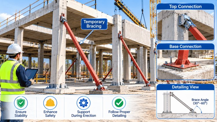
Understanding Temporary Stability Requirements in Precast Construction
Why Temporary Bracing Is Non-Negotiable
Unlike cast-in-place concrete construction, where elements gain strength progressively as part of a continuous monolithic pour, precast elements arrive on site at full strength but without any inherent connection to the structure. Until mechanical connections, grouted joints, or structural topping slabs are in place, each individual element is essentially a free-standing unit subject to wind loads, seismic forces, vibration from adjacent crane picks, and accidental impact.
Industry standards — including PCI MNL-127 (Erector's Manual) and ACI 550 guidelines — mandate that every precast element must be positively braced immediately after placement and remain braced until the permanent structural system can independently resist lateral and eccentric gravity forces. Failure to comply is not merely a code violation; it is a leading contributor to precast erection fatalities.
Stability Demands at Each Erection Phase
Temporary stability requirements vary significantly across the erection sequence. Project teams must evaluate stability at three distinct phases:
Immediately After Set
The element is released from the crane but permanent connections are not yet engaged. Bracing must resist 100% of applicable lateral loads independently.
During Connection Work
Workers are on or near the panel. Dynamic loads from activity, wind gusts, and adjacent picks create combined load scenarios requiring brace capacity verification.
Post-Connection, Pre-Grouting
Mechanical connections may be made but grout or topping hasn't cured. Bracing may remain required until composite action is confirmed by the Engineer of Record.
Why Temporary Stability Planning Matters
Temporary bracing is not simply an erection accessory. It is an engineered life-safety system that protects workers, maintains alignment, prevents progressive collapse, and preserves structural integrity until the completed precast system becomes capable of carrying design loads independently. Every brace, anchor, and attachment point should be designed, installed, inspected, and maintained with the same rigor applied to permanent structural components.
Temporary stability is not achieved when a panel is placed. It is achieved only when the element remains continuously stable through placement, connection, grouting, and final structural integration without relying on chance, crane support, or incomplete permanent connections.
Successful precast erection depends on engineered temporary stability. Every element must remain positively restrained from the moment it leaves the crane until the permanent structural system is fully capable of resisting all required loads.
Selecting the correct bracing system for a given precast element requires understanding the structural demands, available slab bearing capacity, element geometry, and erection sequencing constraints. The following represent the primary brace categories used in precast wall panel bracing applications across North American projects.
Types of Braces, Anchors & Supporting Systems
Brace placement, connection hardware, and erection drawing coordination determine whether precast panels remain stable during installation. Generic field-verify notes and informal deviations create avoidable safety and liability risks.
Explicit hardware specifications, coordinated brace layouts, defined release criteria, and documented deviations keep precast erection safe and controlled.
Brace Placement, Connection Detailing
& Erection Drawing CoordinationDetail the brace, the anchor, and the release condition before erection begins.
Temporary bracing systems are among the most critical life-safety components of precast erection operations. Even properly engineered systems can encounter site-specific coordination challenges, weather impacts, fabrication deviations, and installation conflicts. Successful projects rely on proactive planning, continuous inspection, disciplined execution, and engineering oversight from the first panel pick through final structural stabilization.
Fabrication tolerances and detailing discrepancies can result in brace inserts being positioned outside their intended attachment zones. Unauthorized field adjustments introduce significant risk and can compromise the engineered bracing design.
Deadman anchors placed on thin slabs, immature concrete, or weak subgrades may not provide the required resistance for temporary brace loads.
Erection bracing systems are frequently designed for temporary wind conditions. Unexpected weather changes can increase loading beyond the design assumptions used during planning.
Congested erection sequences often create conflicts between adjacent braces, reducing installation efficiency and potentially impacting structural effectiveness.
Crane support must remain in place until all required braces are installed, connections are secured, and adjustment procedures are completed and verified.
Inspect braces every day and after severe weather events for loose hardware, bent components, anchor movement, damage, or overstress conditions.
Temporary bracing requirements, erection sequencing, and stabilization procedures must be understood and implemented by qualified site personnel.
Temporary precast bracing is an engineered structural system, not a field adjustment activity. Successful projects depend on coordinated erection plans, properly engineered hardware, qualified supervision, structured inspections, and disciplined communication among fabricators, erectors, and engineers. Investing in thorough planning before the first panel is erected consistently produces safer job sites, fewer coordination conflicts, reduced schedule risk, and more reliable project outcomes.
Common Bracing Challenges, Safety Considerations & Key Takeaways
Insert Mislocations
Inadequate Slab Bearing
Wind Load Exceedances
Brace-to-Brace Interference
Critical Safety Considerations
Never Release the Crane Early
Daily Brace Inspection
Qualified Erection Supervision
Elements of a Successful Bracing Program
Key Takeaways
What's Your Reaction?