Precast Bridge Girder Detailing: Reinforcement, Prestressing & Structural Connections
Precast concrete bridge girders represent one of the most efficient, durable, and quality-controlled solutions in modern bridge construction. By manufacturing structural members in a controlled plant environment, engineers and fabricators can achieve superior concrete quality, tight dimensional tolerances, and consistent prestress forces — delivering bridges that perform reliably for 75 to 100-year design lives with minimal maintenance intervention.
Girder Types, Applications & Prestressing Strand Layouts
Common Precast Girder Types
Selecting the right girder cross-section is the first critical engineering decision, driven by span length, superstructure depth constraints, load requirements, and regional fabricator capabilities.
AASHTO I-Girders (Types I–VI)
The workhorse of highway bridges. Span ranges from roughly 40 ft (Type I) to 160 ft (Type VI). Standardized flanges allow consistent formwork reuse across fabricators nationwide.
Bulb-Tee Girders (BT-54, BT-72, BT-84)
Wide top flanges reduce or eliminate the need for stay-in-place deck forms. Deeper sections extend economical spans to 180+ ft.
Box Beams (Voided Rectangular)
Solid or cored rectangular sections used where superstructure depth is severely restricted — common on grade separations and low-clearance stream crossings.
Decked Bulb-Tee & Double-Tee Girders
Fully precast deck integrated into the section. Ultra-rapid installation with minimal field-cast concrete.
U-Beams (Trough Girders)
Open-top U-shaped sections offering excellent torsional stiffness and an aesthetically pleasing soffit — favored on urban elevated structures.
Prestressing Strand Layout Fundamentals
Prestressing is what distinguishes precast bridge girders from conventionally reinforced members. Properly detailed strand patterns control cracking, camber, and long-term deflection.
Strand Size & Grade: Low-relaxation 0.5-in. or 0.6-in. diameter, 270 ksi (Grade 270) seven-wire strands are the industry standard. Larger 0.6-in. strands allow fewer total strands for equivalent prestress force.
Straight vs. Harped Patterns: Straight patterns are simplest to detail and inspect. Harped (draped) strands reduce end-zone tensile stresses and improve shear capacity — critical for longer spans and heavier loads.
Debonding (Blanketing): Plastic sleeves suppress prestress transfer over a defined length to control top-fiber tensile stresses at release. AASHTO LRFD 5.9.4.3 limits debonded percentages per row and per total.
Cover & Spacing: Minimum 1.5-in. clear cover to strands in aggressive environments; 2-in. preferred. Minimum 1.33× maximum aggregate size clear between strands horizontally and vertically.
Jacking Stress: Typically 0.75 fpu = 202.5 ksi initial jacking stress. Shop drawings must document initial prestress, estimated losses (elastic shortening, creep, shrinkage, relaxation), and final effective prestress.
Coordination Requirement
Strand layout must be coordinated with the stressing abutment geometry, hold-down/hold-up hardware for harped strands, and the fabricator's standard bed lengths. Early coordination prevents costly re-detailing.
Strand Strength
Low-relaxation Grade 270 strand — the AASHTO/PCI standard for bridge girders
Max Practical Span
Achievable with deep bulb-tee sections and optimized strand patterns
Jacking Stress Limit
0.75 fpu maximum initial jacking per AASHTO LRFD 5.9.3
Min. Release f'ci
Minimum concrete compressive strength at prestress transfer — typically 4.5–6 ksi
Successful precast bridge girder design depends on selecting the right section, optimizing the prestressing strategy, and coordinating strand layouts with fabrication capabilities, transport constraints, and long-term structural performance requirements.
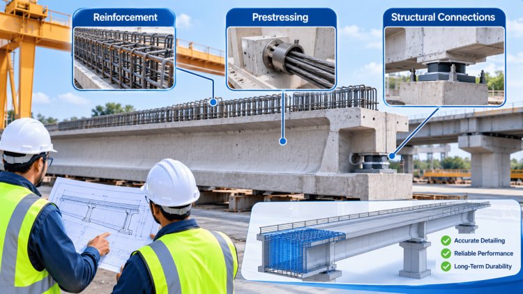
The end regions and connection zones of precast bridge girders concentrate the highest stress demands in the entire superstructure. Detailed reinforcement in these areas is non-negotiable — inadequate detailing leads to splitting cracks at transfer, spalling at bearings, and poor load transfer between girders and substructure elements. Sound connection design integrates structural performance with fabrication practicality.
The end block is a solid or partially solid zone at each girder end that transitions from the thin web to the full bearing width. Confinement reinforcement — typically closed stirrups or U-bars at 2–3 in. spacing — resists the bursting and spalling tensile forces generated as prestress transfers from strand to concrete. AASHTO LRFD Article 5.9.4.4 and PCI Design Handbook provide the split-tension tie design methodology. Longitudinal confinement bars (minimum No. 5) are required along the bottom flange for the transfer length region (approximately 60 strand diameters from the end).
Diaphragms transfer lateral loads between girders, provide torsional stability during construction, and distribute live load. Cast-in-place concrete diaphragms are formed against pocket blockouts or through-holes in the girder web. Structural steel diaphragms (pipe struts, HSS cross-frames) are common in seismic zones for ductile energy dissipation. Embedded connection plates and headed studs must be detailed on both the girder shop drawings and the bridge plans to avoid field conflicts. Diaphragm spacing typically does not exceed L/4 or 40 ft.
Precast girders are most commonly set on plain or laminated elastomeric bearing pads conforming to AASHTO M251. Pad plan dimensions are sized for dead load bearing pressure (typically 800–1,200 psi allowable), rotation capacity, and shear deformation due to thermal movements. Shop drawings must show pad recess dimensions, grout pad details where required, sole plate anchor bolt patterns, and keeper plate or lateral stop details to prevent girder walking under seismic or dynamic loading.
A fully coordinated embedded hardware schedule is one of the most demanding aspects of precast bridge girder shop drawings. Items include: lifting loops and strand lift inserts (designed for static + dynamic lift forces with appropriate factor of safety per PCI Handbook Chapter 8); shear key blockouts for longitudinal CIP closure pours; duct blockouts for post-tensioning tendons in spliced girder systems; grounding cables; drainage tube inserts; and railing anchor channels. All hardware must be shown on the shop drawing with dimensional tolerances, embedment depths, and load ratings.
End Blocks, Diaphragms, Bearing Connections & Embedded Components
End Block Detailing
Intermediate & End Diaphragms
Bearing Pads & Sole Plates
Embedded Hardware & Blockouts
Precast bridge girder shop drawings are the bridge between design intent and fabricated product. They must be complete, internally consistent, and coordination-checked against the bridge contract plans before any concrete is placed. Errors found in the shop drawing review stage cost a fraction of the rework required after casting. Explore structural engineering resources and detailing references for precast fabrication at Consac.com.
Complete, internally consistent shop drawings and disciplined PCI-certified fabrication controls prevent costly rework after casting.
Shop Drawings, Fabrication
Requirements & Quality ControlReview the drawings before the concrete is placed.
A precast bridge girder's most demanding structural conditions often occur before it ever carries traffic. Transportation, lifting operations, storage, and erection introduce temporary stresses, stability challenges, and dynamic loading scenarios that must be engineered with the same level of rigor as the completed bridge structure. Successful projects integrate transportation planning, rigging design, and erection sequencing into the overall girder engineering process from the very beginning.
Long-span bridge girders routinely exceed standard transportation limits, requiring specialized hauling equipment, route analysis, and permit coordination. Transportation engineering must consider vehicle length, axle loading, turning radii, roadway restrictions, bridge postings, overhead clearances, and local infrastructure limitations.
Shop drawings should clearly identify girder weights, center-of-gravity locations, transport support points, tie-down positions, and bunk locations. These locations must align with transportation stability analyses to minimize the risk of rollover, distortion, or handling damage.
Temporary lifting systems must safely support the full dead weight of the girder while accounting for dynamic amplification effects during handling operations. Lift inserts, rigging hardware, spreader systems, and lifting configurations directly influence internal stress patterns during erection.
Long and slender girders require special attention to lateral stability. Compression flanges, torsional resistance, and lateral-torsional buckling behavior must be evaluated while the member is suspended from lifting points and subjected to handling loads.
Erection engineering should define placement sequences, crane positions, temporary bracing requirements, survey procedures, and stabilization methods before construction begins. The initial girders erected on a bent cap frequently experience their least stable condition before adjacent members and diaphragms are installed.
Temporary bracing systems, kickers, alignment controls, and survey verification procedures should be incorporated into erection planning to maintain stability throughout construction and prior to deck placement.
Coordinate strand patterns, lifting hardware, embedded components, and transportation support locations on a single integrated set of fabrication documents. Resolving conflicts before shipment is significantly less costly than addressing them during erection.
Lateral stability frequently governs long-span girders during transportation, lifting, and early erection. Temporary loading conditions should be evaluated as rigorously as final service loads.
PCI-certified manufacturing processes and disciplined quality assurance remain the foundation of durable bridge superstructures. Field repairs cannot replace quality achieved during fabrication.
Bearing elevations, girder alignment data, camber measurements, temporary support records, and final as-built surveys should be documented throughout erection. Minor deviations can often be corrected through shimming or grout adjustments, but only when detected and recorded before deck placement permanently locks the bridge geometry into position.
These records provide essential quality assurance evidence, support future maintenance activities, and establish the final benchmark geometry of the completed bridge structure.
Transportation, lifting, storage, and erection are not logistical afterthoughts—they are structural engineering load cases. Precast bridge girders often experience their most critical temporary stresses long before traffic loading begins. Successful bridge projects recognize this reality, integrating transportation engineering, rigging analysis, erection sequencing, and quality assurance documentation into a single coordinated strategy that protects structural integrity from the casting bed to the completed bridge deck.
Transportation, Lifting & Bridge Erection Considerations
Transportation Planning & Permit Routing
Lifting Hardware & Rigging Design
Bridge Erection Sequence & Temporary Stability
Transportation-to-Erection Workflow
Key Engineering Takeaways
Survey Records & Quality Documentation
Final Engineering Principle
What's Your Reaction?