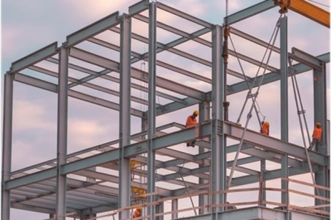
Floor Deck Package Review for Fabricators and Contractors

A technical deep-dive into the shop and field detailing disciplines that separate a clean floor deck package from one that generates RFIs, delays, and costly rework. This presentation covers what experienced fabricators and contractors need to verify, coordinate, and execute on composite and non-composite floor deck systems — from package intake through final inspection.

Floor Deck Package Review for Fabricators and Contractors
Floor Deck • Submittal Review • Shop Readiness

What a Floor Deck Package Actually Contains

Before any steel hits the shop floor, a thorough package review is the first line of defense against downstream problems. A complete floor deck submittal package typically includes erection drawings, material specifications, fastener schedules, and approval stamps — but knowing what to look for within each document is where expertise matters.

Package Review Architecture

Four Document Layers Must Align Before Release

01
Erection Drawings
02
Material Specifications
03
Fastener & Attachment Schedules
04
Engineer of Record Approvals
Drawing
Package Component

Erection Drawings

Plan views with deck panel layout, bundle drop locations, pour stop details, and sidelap/endlap fastener pattern callouts. Verify orientation arrows match structural framing direction and that sheet lengths account for bearing minimums at each support.

Erection Drawing Review
Panel Layout
•
Bundle Drops
•
Pour Stops
•
Fastener Patterns
Verify orientation arrows match structural framing direction and confirm sheet lengths maintain bearing minimums at each support.

Fabrication Release Control

Critical Detailing Checks Before Fabrication Release

Releasing a floor deck package to fabrication without resolving detailing conflicts is one of the most expensive mistakes a shop can make. The following are the non-negotiable review checkpoints that should be completed — and documented — prior to any material being cut, rolled, or ordered.

Fabrication Gate

Resolve → Document → Release

NO OPEN CONFLICTS
Review
Verify details
→
Resolve
Close conflicts
→
Release
Fabrication ready
Non-Negotiable Review

Three Detailing Gates Before Material Release

01
BEARING
1.5" / 3"
Bearing & End-Lap Requirements

SDI minimum bearing for floor deck is typically 1.5" on steel and 3" on concrete or masonry. Verify each panel's end condition against the structural framing plan. End-lap length, when panels don't span the full bay, must meet both the manufacturer's published minimums and the EOR's callout — these sometimes conflict. When they do, the more conservative governs unless a written waiver exists.

Critical interference check: Confirm end-lap panels are not located at columns or moment connections where embedded plates, anchor rods, or through-bolts would interfere with the lap zone.
Orientation + Forming

Deck Orientation & Pour Stop Coordination

Flute orientation directly affects composite behavior, load distribution, and concrete volume. Confirm that deck runs perpendicular to primary framing unless the engineer has explicitly approved parallel orientation with supporting calculations.

Pour stops (closure angles, Z-closures, or formed edge conditions) must be dimensioned to the correct slab thickness and should account for camber in supporting beams.

High-Risk Locations
Re-entrant Corners
Stair Openings
Shaft Edges
Detailing warning: Incomplete pour-stop details at these locations commonly push coordination into the field.
02
ORIENTATION
Flutes
Pour Stops
Camber
03
Connection Interface

Shear Stud Clearance Zones

CHECK BEFORE RELEASE

Even when shear stud design is handled separately, the deck detailer must confirm that the flute geometry doesn't conflict with stud placement requirements. Through-deck welding in 3" deep profiles requires specific flute width minimums.

Geometry Review
Check flute geometry against required stud placement and identify marginal conditions.
Beam Flag
Flag beams where structural drawings show studs but flute geometry may be marginal.
Release rule: Any uncertain stud/deck interface should be resolved before fabrication rather than discovered after material production.
Final Review Matrix

What Must Be Closed Before Release

Bearing
End bearing and end-lap conditions verified.
CHECK
Orientation
Flutes, framing direction, pour stops, and camber coordinated.
CHECK
Stud Clearance
Flute geometry confirmed compatible with stud requirements.
CHECK
GO
Fabrication Release Gate

Cut, Roll, and Order Only After the Detail Is Closed

A fabrication release should represent a coordinated and documented design state. Bearing, end laps, deck orientation, pour stops, special edge conditions, camber, and shear stud clearance should all be resolved before material is committed. The objective is simple: move uncertainty out of fabrication and into the review process, where it can be corrected without production cost.

Release principle: No unresolved detailing conflict should become a fabrication problem.

Submittal Quality

Common Package Deficiencies
That Drive RFIs

Field RFIs on floor deck packages almost always trace back to one of a handful of recurring deficiencies in the original submittal. Tracking these patterns reduces both RFI volume and the cost of resolving them after concrete has been placed.

RFI
RECURRING DEFICIENCIES

Field RFIs on Floor Deck Packages Almost Always Trace Back to One of a Handful of Recurring Deficiencies in the Original Submittal

Missing or ambiguous deck schedules, inconsistent gauge callouts, unresolved haunch and infill conditions, and fastener patterns not tied to diaphragm tables are the most common package deficiencies that drive field RFIs. Tracking these patterns reduces both RFI volume and the cost of resolving them after concrete has been placed. Require color-coded or hatched plans with explicit legends before releasing erection drawings; ensure every gauge referenced matches material certification; identify custom infill strips during review; and cross-reference fastener callouts against diaphragm schedules during package review.

TOP RFI DRIVER

Missing or Ambiguous Deck Schedule

Packages that reference multiple deck profiles across a single floor level—common in mixed-use or podium structures—must include a clearly keyed deck schedule tied to plan zones. When the schedule is missing or the zone boundaries are unclear, field crews default to the most common profile, which is frequently wrong.

Where it occurs: Mixed-use or podium structures with multiple deck profiles across a single floor level.
Required detail: Clearly keyed deck schedule tied to plan zones with explicit legend.
Common failure: Schedule missing or zone boundaries unclear—field crews default to most common profile, which is frequently wrong.
Prevention: Require a color-coded or hatched plan with an explicit legend before releasing erection drawings—this eliminates ambiguity and prevents field crews from defaulting to the wrong profile.
NON-CONFORMANCE RISK

Inconsistent Gauge Callouts

Design drawings often list minimum gauge; the fabricator's submittal may propose an equivalent or upgraded gauge. If the EOR's approval letter doesn't explicitly confirm the as-submitted gauge, the field inspector has no basis for acceptance.

Design vs. submittal: Design drawings list minimum gauge; fabricator's submittal may propose equivalent or upgraded gauge.
Required confirmation: EOR approval letter must explicitly confirm the as-submitted gauge—otherwise field inspector has no basis for acceptance.
Consequence: Discrepancies between erection drawing gauge and material certification (mill cert) trigger non-conformance reports.
Prevention: Ensure that every gauge referenced in the erection drawing matches the material certification (mill cert) for the delivered material—discrepancies here trigger non-conformance reports and field RFIs.
SCHEDULE IMPACT

Unresolved Haunch & Infill Conditions

Sloped decks, transfer levels, and composite beams with haunches require custom infill strips or closure pieces that are rarely detailed in standard packages. These items must be identified during the review phase and either shop-fabricated or flagged as field-formed work with explicit owner and EOR acceptance.

Where it occurs: Sloped decks, transfer levels, and composite beams with haunches—conditions requiring custom infill strips or closure pieces.
Required action: Identify during review phase; either shop-fabricate or flag as field-formed work with explicit owner and EOR acceptance.
Common failure: Leaving infill conditions to "field verify" almost always results in schedule impacts and field RFIs.
Prevention: Custom infill strips and closure pieces must be identified during the review phase and either shop-fabricated or flagged as field-formed work with explicit owner and EOR acceptance—leaving them to "field verify" almost always results in schedule impacts.
INSPECTION COMPLIANCE

Fastener Pattern Not Tied to Diaphragm Table

The structural drawings typically include a diaphragm schedule that assigns fastener patterns (e.g., 36/4 for high-shear zones) by floor zone. If the erection drawing fastener callout doesn't explicitly reference—or reproduce—this schedule, field crews have no reliable way to verify compliance during inspection.

Structural requirement: Diaphragm schedule assigns fastener patterns (e.g., 36/4 for high-shear zones) by floor zone.
Required linkage: Erection drawing fastener callout must explicitly reference or reproduce the diaphragm schedule.
Common failure: Fastener callout doesn't reference diaphragm schedule—field crews have no reliable way to verify compliance during inspection.
Prevention: Cross-reference both documents during package review—ensure erection drawing fastener callout explicitly references or reproduces the diaphragm schedule to prevent inspection disconnects and field RFIs.

Package Deficiencies and Their Consequences

Deficiency Required Detail Common Failure Consequence
Missing/Ambiguous Deck Schedule Clearly keyed deck schedule tied to plan zones with explicit legend Schedule missing or zone boundaries unclear—field crews default to most common profile Wrong profile installed; field RFIs; potential rework after concrete placement
Inconsistent Gauge Callouts EOR approval letter explicitly confirms as-submitted gauge; erection drawing gauge matches mill cert EOR approval doesn't confirm as-submitted gauge; discrepancies between erection drawing and mill cert Field inspector has no basis for acceptance; non-conformance reports triggered
Unresolved Haunch & Infill Custom infill strips identified during review; shop-fabricated or flagged as field-formed with explicit acceptance Infill conditions left to "field verify" without explicit owner and EOR acceptance Schedule impacts; field RFIs; work stoppage awaiting resolution
Fastener Pattern Disconnect Erection drawing fastener callout explicitly references or reproduces diaphragm schedule Fastener callout doesn't reference diaphragm schedule—field crews cannot verify compliance Inspection failures; field RFIs; potential re-fastening required
RFI REDUCTION

Tracking These Patterns Reduces Both RFI Volume and the Cost of Resolving Them After Concrete Has Been Placed

PREVENTIVE
Deck Schedule Color-coded plan with explicit legend before releasing erection drawings
Gauge Callouts Erection drawing gauge matches mill cert; EOR confirms as-submitted gauge
Haunch/Infill Identify during review; shop-fabricate or flag as field-formed with explicit acceptance
Fastener Pattern Cross-reference erection drawing against diaphragm schedule during package review
Field RFIs on floor deck packages almost always trace back to one of a handful of recurring deficiencies in the original submittal. Tracking these patterns reduces both RFI volume and the cost of resolving them after concrete has been placed.
COST IMPACT

Resolving RFIs After Concrete Has Been Placed Is Far More Costly Than Preventing Them During Package Review

The cost of resolving field RFIs escalates dramatically after concrete placement. Preventing RFIs through thorough package review—before erection drawings are released—is the most cost-effective risk mitigation strategy.

Prevention vs. remediation Missing deck schedules, inconsistent gauge callouts, unresolved haunch and infill conditions, and fastener patterns not tied to diaphragm tables are the most common package deficiencies that drive field RFIs. Tracking these patterns reduces both RFI volume and the cost of resolving them after concrete has been placed. Resolving RFIs after concrete placement requires core drilling, patching, structural re-analysis, and potential work stoppage—costs that far exceed the effort required to prevent them during package review.

The Package Deficiencies Principle

Field RFIs on floor deck packages almost always trace back to one of a handful of recurring deficiencies in the original submittal. Tracking these patterns reduces both RFI volume and the cost of resolving them after concrete has been placed. Four deficiencies are the most common drivers: (1) Missing or Ambiguous Deck Schedule—packages that reference multiple deck profiles across a single floor level (common in mixed-use or podium structures) must include a clearly keyed deck schedule tied to plan zones; when the schedule is missing or zone boundaries are unclear, field crews default to the most common profile, which is frequently wrong; require a color-coded or hatched plan with an explicit legend before releasing erection drawings. (2) Inconsistent Gauge Callouts—design drawings often list minimum gauge; the fabricator's submittal may propose an equivalent or upgraded gauge; if the EOR's approval letter doesn't explicitly confirm the as-submitted gauge, the field inspector has no basis for acceptance; ensure that every gauge referenced in the erection drawing matches the material certification (mill cert) for the delivered material—discrepancies here trigger non-conformance reports. (3) Unresolved Haunch & Infill Conditions—sloped decks, transfer levels, and composite beams with haunches require custom infill strips or closure pieces that are rarely detailed in standard packages; these items must be identified during the review phase and either shop-fabricated or flagged as field-formed work with explicit owner and EOR acceptance; leaving them to "field verify" almost always results in schedule impacts. (4) Fastener Pattern Not Tied to Diaphragm Table—the structural drawings typically include a diaphragm schedule that assigns fastener patterns (e.g., 36/4 for high-shear zones) by floor zone; if the erection drawing fastener callout doesn't explicitly reference or reproduce this schedule, field crews have no reliable way to verify compliance during inspection; cross-reference both documents during package review to prevent this disconnect. Resolving RFIs after concrete placement is far more costly than preventing them during package review.

Construction Quality Control

Field Inspection & Acceptance Criteria

Passing a floor deck inspection is not just about the deck being down and flat. Inspectors — whether third-party special inspection, owner's representative, or AHJ — will be verifying specific measurable criteria. Fabricators and erectors who understand the acceptance thresholds before installation begins avoid the most common sources of rejection.

Structural Attachment Verification

Weld patterns must be verified against the approved erection drawing. For arc spot welds, inspectors review burn-through diameter and weld quality using SDI acceptance criteria. Power-actuated fasteners must comply with the applicable ICC-ES evaluation report, including approved fastener model, powder load, and installation tool. Random pull testing may be required by project specifications or inspector discretion.

Sidelap Fastener Compliance

Sidelap connectors such as screws, button punches, and welds are frequently under-installed because they are less visible than structural welds. Inspectors verify connector counts and spacing throughout each sidelap run. Any bay falling below the specified pattern is typically rejected. Proper crew briefing before mobilization significantly reduces punch-list deficiencies.


Deck Condition & Damage Assessment

Installed deck panels are examined for kinked flutes, torn edges, excessive camber, coating damage, and other handling-related defects. SDI and project-specific specifications define acceptable damage limits. Panels with compromised structural cross-sections generally require replacement rather than repair. Replacement procedures and warranty responsibilities should be coordinated prior to concrete placement.

Concrete Placement Readiness Checklist

✅ All openings temporarily covered or permanently framed per drawing.
✅ Pour stops fully secured with required fastener spacing.
✅ Camber in composite beams verified within allowable tolerance before loading.
✅ Deck surface swept clean with no standing water or construction debris remaining in flutes.
✅ Welded wire reinforcement (WWR) installed in accordance with slab drawings and specified cover requirements.
✅ Pre-pour inspection sign-off obtained from the EOR or designated inspector.
⚠

Critical Acceptance Requirement

Never proceed to concrete placement without a signed pre-pour inspection record. Verbal approvals are not defensible in the event of a post-pour structural question, quality dispute, warranty claim, or forensic investigation. Written documentation provides the formal record needed to demonstrate compliance with project requirements and accepted construction practice.

Floor Deck • Package Review • Pre-Release Control

Package Review: A Fabricator's Pre-Release Checklist

Distilled from the detailing disciplines covered in this presentation, the following checklist represents the minimum standard a floor deck package should meet before material is ordered, cut, or shipped. Use it at the shop level during submittal review and again at the pre-erection coordination meeting with the GC and EOR.

Pre-Release Quality Gate

Verify the Package Before Material Moves

Review
→
Verify
→
Document
→
Release
Minimum Review Standard

Checks Before 
Material Release

03
Drawing
Completeness

Drawing Completeness

Deck schedule keyed to plan zones
All profiles, gauges, and coatings listed
Pour stop details at all slab edges
Openings dimensioned and closures shown

What's Your Reaction?

like

dislike

love

funny

angry

sad

wow