How Composite Deck Drawings Support Construction Scheduling

In the fast-moving world of structural steel construction, composite deck drawings are far more than a drafting deliverable — they are a critical scheduling instrument. When properly detailed and issued on time, these drawings establish the sequencing logic that keeps structural steel erectors, concrete crews, MEP rough-in teams, and inspectors aligned across every phase of a project. A drawing set that arrives late, incomplete, or with unresolved conflicts doesn't just slow down one trade — it creates a cascading delay that ripples through the entire project schedule. This presentation explores the direct relationship between composite deck drawing quality, issuance timing, and construction schedule performance — with practical guidance for schedulers, project managers, and design coordinators who depend on these documents to build accurate, defensible timelines.
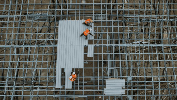
How Composite Deck Drawings Support Construction Scheduling
Composite Deck • Drawing Data • Field Scheduling

What Composite Deck Drawings Actually Contain

Understanding the scheduling implications of composite deck drawings starts with understanding what these documents communicate. A wellprepared composite deck drawing set is dense with information that directly governs field operations — and every element has a scheduling consequence.

Drawing Information Architecture

Three Data Layers Drive Field Readiness

01
Structural &
Layout Data
02
Concrete & Shear
Connection Data
03
Submittal &
Coordination References
01
Drawing Layer 01

Structural & Layout Data

01
Deck type designation (e.g., 2VLI, 3VLI, 1.5B) and gauge by zone
02
Deck span directions and orientation relative to structural framing
03
Bearing conditions at supports: beam flanges, walls, or pour stops
04
Edge conditions, closures, and flute direction at perimeter
05
Location and extent of all deck openings, with reinforcement callouts
What the Layout Defines
Deck Type
•
Direction
•
Bearing
•
Openings
02
Concrete
& Shear
Connection Data
Drawing Layer 02

Concrete & Shear Connection Data

Concrete topping thickness, lightweight vs. normal weight designation
Shear stud layout, diameter, and quantity per beam (governs composite beam behavior)
Welded wire reinforcement or rebar mat specifications
Control joint locations and construction joint designations
Required concrete compressive strength (f'c) at pour and at loading
Composite Floor Coordination
Deck
+
Shear
Connection
+
Concrete
Requirements
Drawing Layer 03

Submittal & Coordination References

01 Cross-references to structural engineer drawings and specifications
02 Deck manufacturer product designations for submittal matching
03 Weld pattern callouts for deck-to-structure attachments
03
Reference
Control
Coordination Chain

The Deck Drawing Does Not Stand Alone

Structural Drawings
↔
Deck Submittal
↔
Field Installation
Field Readiness Gate

Every Data Point Must Be Resolved Before Work Proceeds

Resolve
→
Review
→
Approve
One Unresolved Item Can Stop Installation

Typical Schedule Stop Conditions

01 An unresolved opening location
02 An unapproved deck gauge substitution
03 A missing pour stop detail
Scheduling Consequence

Each of these data points must be resolved, reviewed, and approved before field work can proceed. Any one of them — an unresolved opening location, an unapproved deck gauge substitution, a missing pour stop detail — is sufficient to stall installation or create a costly rework condition.

Drawing Readiness Drives Schedule Readiness

Resolve the Information Before the Field Depends on It.

Complete Data
→
Approved Drawings
→
Field Ready

Construction Scheduling

The Drawing-to-Schedule Pipeline: Key Milestone Dependencies

Composite deck drawings don't exist in isolation — they sit inside a tightly coupled milestone chain where each upstream deliverable unlocks downstream field activity. Schedulers must map these dependencies explicitly or risk building a schedule that looks logical on paper but collapses in the field.

Dependency Chain

Design → Approval → Release → Procurement → Field

SCHEDULE GATES
01
Structural Design
02
IFA Review
03
AFC Release
04
Fabrication
05
Installation + Pour
01
DESIGN

Structural Steel Design Complete

The structural engineer of record (EOR) finalizes beam layouts, composite beam designations, and slab edge conditions. This governs every downstream deck drawing decision, including span direction and shear stud requirements. No deck drawing can be started in earnest without a stable structural model.

Dependency gate: A stable structural model is the prerequisite for meaningful deck detailing.
Review Window

Deck Drawings Issued for Approval (IFA)

The deck detailer or fabricator issues drawings to the EOR and general contractor for review. This submittal must be tracked in the project schedule with a defined review window — typically 10 to 15 business days for first submittal. RFIs generated during this period must be tracked and resolved before approval is granted.

Schedule activity: The review period and RFI resolution are explicit predecessor activities, not untracked administrative time.
02
IFA
10–15
Business Days
03
RELEASE

Approved-for-Construction (AFC) Drawings Issued

Approved drawings are released to the erector and deck installer. This is the critical schedule gate: field crews cannot legally or safely install deck to a non-approved drawing. AFC issuance date should be resource-loaded against the deck installation start date with buffer for procurement lead time.

Critical Gate
AFC release unlocks field installation and should be linked directly to the installation start milestone.
Procurement Dependency

Deck Material Fabricated & Delivered

Composite deck panels are manufactured to specific lengths and widths per approved drawings. Lead times typically run 3 to 6 weeks from order to delivery, depending on gauge, profile, and plant capacity.

Scheduler Action
Insert the procurement activity immediately upon AFC issuance — not after delivery.
04
FABRICATE
3–6 Weeks
Field Execution

Deck Installation & Concrete Pour

05

Field installation of deck panels, pour stops, and shear studs precedes concrete placement. The concrete pour itself has its own predecessor chain: shear stud inspection, deck attachment inspection, formwork sign-off, and MEP rough-in clearance. Each predecessor is a schedule activity that must be sequenced and duration-estimated.

01
Stud Inspection
02
Deck Inspection
03
Formwork Sign-Off
04
MEP Clearance
Scheduling principle: Do not collapse these checks into a single “ready for pour” activity. Each predecessor should be sequenced, assigned, and duration-estimated.
Scheduler's Control Panel

Dependencies That Should Never Be Hidden

Design Stability
Structural steel design must be stable before meaningful deck detailing begins.
Review Duration
IFA review, RFIs, and approval must be represented explicitly in the schedule.
Procurement Lead
The 3–6 week fabrication window begins with the approved release, not with material arrival.
Pour Readiness
Inspections, formwork sign-off, and MEP clearance are real predecessor activities.
Final Scheduling Principle

Build the Schedule Around the Dependencies

The deck installation date is only as reliable as the chain that feeds it. A robust schedule connects structural design completion, IFA review, RFI resolution, AFC release, procurement lead time, fabrication, delivery, installation, inspections, and concrete-pour readiness into one visible dependency network.

Schedule Risk

Common Drawing Gaps That
Destroy Schedule Float

Even a single ambiguous or missing detail in a composite deck drawing set can consume days or weeks of schedule float. The following issues are among the most frequently cited causes of deck installation delays on commercial and industrial construction projects. Recognizing these patterns during the drawing review phase—rather than discovering them in the field—is one of the highest-leverage scheduling risk mitigation strategies available.

FLOAT
⚠️
SCHEDULE RISK PATTERNS

A Single Uncoordinated Shaft Opening on a Typical Floor Plate Can Delay an Entire Level by 5 to 10 Working Days

Unresolved or undersized deck openings, missing pour stop and edge condition details, deck gauge or span substitutions without EOR sign-off, and shear stud layout conflicts with MEP routing are among the most frequently cited causes of deck installation delays. Recognizing these patterns during the drawing review phase—rather than discovering them in the field—is one of the highest-leverage scheduling risk mitigation strategies available. Even a single ambiguous or missing detail in a composite deck drawing set can consume days or weeks of schedule float.

DELAY RISK: 5–10 DAYS

Unresolved or Undersized Deck Openings

Openings for mechanical shafts, plumbing penetrations, and electrical conduit runs must be shown on deck drawings with exact dimensions and edge reinforcement details. When openings are shown as "by others" or lack framing callouts, the deck installer cannot proceed in those zones—and MEP rough-in is blocked behind them.

Required details: Exact dimensions and edge reinforcement details for all mechanical shafts, plumbing penetrations, and electrical conduit runs.
Common gap: Openings shown as "by others" or lacking framing callouts—deck installer cannot proceed in those zones.
Downstream impact: MEP rough-in is blocked behind deck installation; entire floor plate work sequence is disrupted.
Schedule impact: A single uncoordinated shaft opening on a typical floor plate can delay an entire level by 5 to 10 working days while the EOR and MEP engineers coordinate a resolution.
CRITICAL PATH IMPACT

Missing Pour Stop and Edge Condition Details

Pour stops—the metal closures at slab edges—must be specified for type, height, and attachment method. When pour stop details are absent or generic, the erector must pause work, submit an RFI, and await a response before installing edge conditions.

Required specs: Type, height, and attachment method for all pour stops at slab edges.
Common gap: Pour stop details absent or generic—erector must pause work and submit RFI before proceeding.
Critical path: Particularly impactful at building perimeter locations where pour stop installation is on the critical path to concrete placement.
Schedule impact: When pour stop details are absent or generic, the erector must pause work, submit an RFI, and await a response before installing edge conditions—delaying concrete placement at perimeter locations on the critical path.
SUBMITTAL REJECTION RISK

Deck Gauge or Span Substitutions Without EOR Sign-Off

Material shortages or lead time pressures sometimes prompt requests to substitute a specified deck gauge or profile for an available alternative. If the deck drawing reflects the substitution before the EOR has issued written acceptance, the submittal will be rejected—restarting the approval clock and potentially delaying delivery of the correct material.

Common trigger: Material shortages or lead time pressures prompt requests to substitute specified deck gauge or profile for available alternative.
Required step: EOR must issue written acceptance before deck drawing reflects substitution—otherwise submittal will be rejected.
Consequence: Submittal rejection restarts the approval clock and potentially delays delivery of the correct material.
Schedule risk: Schedulers should treat unapproved substitutions as a schedule risk event and flag them proactively in risk registers—submittal rejection restarts the approval clock and potentially delays delivery of correct material.
FIELD MODIFICATION RISK

Shear Stud Layout Conflicts with MEP Routing

Shear studs welded to the tops of composite beams must not conflict with overhead MEP systems. When duct runs or conduit paths are not coordinated against the structural drawings before deck drawings are finalized, the shear stud pattern shown on the deck drawing may be invalidated by MEP coordination drawings issued weeks later.

Coordination requirement: Shear studs welded to tops of composite beams must not conflict with overhead MEP systems—duct runs and conduit paths must be coordinated before deck drawings are finalized.
Common gap: Duct runs or conduit paths not coordinated against structural drawings before deck drawings finalized—shear stud pattern may be invalidated by MEP coordination drawings issued weeks later.
Consequence: Field modifications required, additional EOR review needed, and potential re-analysis of composite beam capacity.
Schedule impact: When shear stud patterns are invalidated by later MEP coordination drawings, field modifications, additional EOR review, and potential re-analysis of composite beam capacity are required—consuming schedule float and delaying deck installation.

Drawing Gaps and Their Schedule Impact

Drawing Gap Required Detail Common Gap Schedule Impact
Unresolved Deck Openings Exact dimensions and edge reinforcement details for all mechanical shafts, plumbing penetrations, and electrical conduit runs Openings shown as "by others" or lacking framing callouts 5–10 working days delay per floor level while EOR and MEP engineers coordinate resolution
Missing Pour Stop Details Type, height, and attachment method for all pour stops at slab edges Pour stop details absent or generic—erector must pause and submit RFI Critical path delay at building perimeter locations—concrete placement blocked
Unapproved Substitutions EOR written acceptance before deck drawing reflects gauge or profile substitution Deck drawing reflects substitution before EOR written acceptance issued Submittal rejection restarts approval clock; delays delivery of correct material
Shear Stud Conflicts Duct runs and conduit paths coordinated against structural drawings before deck drawings finalized MEP coordination drawings issued weeks later invalidate shear stud pattern Field modifications, additional EOR review, potential re-analysis of composite beam capacity
RISK MITIGATION

Recognizing These Patterns During Drawing Review—Rather Than in the Field—Is One of the Highest-Leverage Scheduling Risk Mitigation Strategies Available

PREVENTIVE
Openings 5–10 days delay per floor; exact dimensions and edge reinforcement required
Pour Stops Critical path at perimeter; type, height, attachment method required
Substitutions EOR written acceptance required before drawing reflects substitution
Shear Studs Coordinate MEP routing before deck drawings finalized; avoid field modifications
Even a single ambiguous or missing detail in a composite deck drawing set can consume days or weeks of schedule float. Recognizing these patterns during the drawing review phase—rather than discovering them in the field—is one of the highest-leverage scheduling risk mitigation strategies available.
HIGHEST-LEVERAGE STRATEGY

Recognize Drawing Gaps During Review—Not in the Field

The highest-leverage scheduling risk mitigation strategy is to identify and resolve drawing gaps during the drawing review phase—before construction begins. Discovering these issues in the field consumes schedule float that cannot be recovered.

Preventive vs. reactive Unresolved deck openings, missing pour stop details, unapproved substitutions, and shear stud conflicts are among the most frequently cited causes of deck installation delays on commercial and industrial construction projects. Recognizing these patterns during the drawing review phase—rather than discovering them in the field—is one of the highest-leverage scheduling risk mitigation strategies available. Even a single ambiguous or missing detail in a composite deck drawing set can consume days or weeks of schedule float—float that cannot be recovered once lost.
⚠️

The Drawing Gaps Principle

Even a single ambiguous or missing detail in a composite deck drawing set can consume days or weeks of schedule float. Four drawing gaps are among the most frequently cited causes of deck installation delays on commercial and industrial construction projects: (1) Unresolved or Undersized Deck Openings—openings for mechanical shafts, plumbing penetrations, and electrical conduit runs must be shown on deck drawings with exact dimensions and edge reinforcement details; when openings are shown as "by others" or lack framing callouts, the deck installer cannot proceed in those zones and MEP rough-in is blocked behind them; a single uncoordinated shaft opening on a typical floor plate can delay an entire level by 5 to 10 working days while the EOR and MEP engineers coordinate a resolution. (2) Missing Pour Stop and Edge Condition Details—pour stops (metal closures at slab edges) must be specified for type, height, and attachment method; when pour stop details are absent or generic, the erector must pause work, submit an RFI, and await a response before installing edge conditions; this is particularly impactful at building perimeter locations where pour stop installation is on the critical path to concrete placement. (3) Deck Gauge or Span Substitutions Without EOR Sign-Off—material shortages or lead time pressures sometimes prompt requests to substitute a specified deck gauge or profile for an available alternative; if the deck drawing reflects the substitution before the EOR has issued written acceptance, the submittal will be rejected, restarting the approval clock and potentially delaying delivery of the correct material; schedulers should treat unapproved substitutions as a schedule risk event and flag them proactively in risk registers. (4) Shear Stud Layout Conflicts with MEP Routing—shear studs welded to the tops of composite beams must not conflict with overhead MEP systems; when duct runs or conduit paths are not coordinated against the structural drawings before deck drawings are finalized, the shear stud pattern shown on the deck drawing may be invalidated by MEP coordination drawings issued weeks later, requiring field modifications, additional EOR review, and potential re-analysis of composite beam capacity. Recognizing these patterns during the drawing review phase—rather than discovering them in the field—is one of the highest-leverage scheduling risk mitigation strategies available.

Project Controls & Scheduling

Scheduling Best Practices: Building the Deck Drawing Workflow into Your CPM Schedule

A Critical Path Method (CPM) schedule that treats composite deck drawings as a single line item — "deck submittals" — is not granular enough to protect the project from drawing-driven delays. The following best practices, drawn from standard industry scheduling methodology and composite deck project experience, provide a framework for integrating the deck drawing workflow into a defensible, executable schedule.

1

Break Submittals Down by Floor and Zone

Rather than scheduling one deck submittal for the entire building, break the submittal package into floor-by-floor or zone-by-zone activities. This allows phased approval and early AFC issuance for lower floors while upper floors are still under review — maintaining erection momentum and enabling earlier concrete pours on completed levels.

2

Model the Review Cycle Realistically

Build the actual review cycle into your schedule: IFA issuance, EOR review period (10–15 business days), response issuance, revision period (5–10 business days for revise-and-resubmit), and AFC issuance. Compressing these activities on the baseline schedule without contractual backup creates instant float problems when the first RFI is logged.

3

Link Procurement Directly to AFC Dates

Deck material procurement activities — purchase order issuance, fabrication, shipping, and delivery — should be logically linked to AFC drawing issuance with a start-to-start relationship and lead time lag. Schedulers who link procurement to "planned" AFC dates rather than actual AFC dates expose the project to material availability risk with no early warning indicator.

4

Assign Drawing Milestones as Contract Deliverables

Where possible, negotiate IFA and AFC drawing issuance dates as contractual milestones with the deck subcontractor or detailer. This creates accountability and provides the general contractor with documented notice when drawing deliverables slip — essential for preserving delay claim rights and protecting the owner's schedule interest.

5

Track RFIs Against Specific Drawing Activities

Every RFI related to deck drawings should be linked to the schedule activity it affects. RFI logs that exist only in project management software, disconnected from the CPM schedule, cannot be used to demonstrate schedule impact. Integration of RFI status into the schedule update cycle is a mark of a high-functioning project controls team.

6

Buffer the Concrete Pour Activity

Insert a defined buffer between deck installation complete and concrete pour authorization. This buffer absorbs inspection time, MEP sign-off, shear stud inspection, and any late punch-out of pour stop conditions. A 5-to-10-day buffer on a standard floor plate is common practice on well-run projects and prevents the concrete crew from being mobilized to a floor that isn't ready.

Recommended Deck Drawing Schedule Flow

IFA Drawing Issue
EOR Review
Revision Cycle
AFC Release
Procurement
Deck Installation
5–10 Day Buffer
Concrete Pour

Drawing Quality • CPM Scheduling • Field Readiness

Key Takeaways: Drawing Quality is a Schedule Asset

Composite deck drawings are not a passive output of the design process — they are an active driver of construction schedule performance. When drawing quality is high, submittals are phased intelligently, and the review cycle is modeled realistically in the CPM schedule, composite deck installation and concrete placement proceed with minimal disruption. When drawings are incomplete, late, or poorly coordinated, the schedule absorbs the consequences across multiple trades and multiple floors.

Schedule Performance Starts Upstream

Drawing Quality Determines How Reliably the Field Can Move

Quality
Drawings
→
Controlled
Approvals
→
Reliable
Field Progress
Schedule Protection Framework

Four Controls That Protect
Field Momentum

04
01
Detail Quality

Detail Matters

Every missing callout — an opening dimension, a pour stop type, a shear stud layout — is a potential RFI that will consume review time and field productivity. Invest in thorough drawing preparation upfront to protect schedule float downstream.

Missing Callout
→
RFI
→
Review Time
→
Float Exposure
Schedule Control 02

Phase Your Submittals

Floor-by-floor or zone-by-zone submittal packages enable phased AFC issuance and keep erection and concrete crews active while upper-floor drawings complete the approval cycle. Never treat the entire building as a single submittal event.

What's Your Reaction?

like

dislike

love

funny

angry

sad

wow