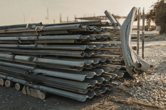
Floor Deck Detailing Near Elevator Cores
A precision-focused guide for structural and detailing engineers navigating one of the most congested, tolerance-sensitive zones in commercial steel framing — where slab edges, slab openings, core walls, and vertical transport infrastructure converge.

Why Elevator Cores Are a High-Stakes Zone for Deck Detailing
Elevator cores are among the most complex and unforgiving areas in a building structure. Structural framing, composite deck systems, elevator requirements, concrete construction, and architectural tolerances converge within a tightly constrained footprint, making coordination failures particularly expensive to identify and correct after construction begins.
More Systems Intersect Here
Than Almost Anywhere Else
Small detailing errors near an elevator core can quickly cascade into framing conflicts, slab issues, hoistway dimensional problems, and costly field modifications that affect multiple trades simultaneously.
The Convergence Problem
Elevator cores must simultaneously support gravity loads from the floor slab, transfer lateral loads into the core wall system, maintain pit and overhead clearance requirements, coordinate with hoistway framing, and provide reliable deck termination conditions. Unlike a typical interior bay, numerous independent systems occupy the same limited space, creating very little tolerance for detailing mistakes.
Systems Converging at the Core
How Small Detailing Errors Become Major Problems
Tolerance Stacking and Why It Bites Here
In open floor bays, construction tolerances are usually absorbed without consequence. At elevator cores, however, independent tolerance chains overlap in the same location. The resulting accumulation can consume available clearances and create dimensional conflicts that are difficult to resolve once construction is underway.
Independent Tolerance Chains
Steel Deck
Installation and positioning tolerances accumulate near core edges.
Structural Steel
Column plumbness and beam alignment tolerances affect framing geometry.
Concrete Slab
Surface elevations and slab edges introduce additional variability.
Elevator System
Hoistway framing requires strict dimensional control.
Wider Bearing Seats
Provide additional tolerance capacity where deck and framing meet the core perimeter.
Adjustable Embeds
Embed systems can absorb dimensional variation while maintaining alignment.
Closure Pour Sequencing
Carefully planned closure pours help accommodate accumulated construction tolerances.
Code and Coordination Overlap
Elevator cores sit at the intersection of structural engineering, architecture, and elevator-system design. Successful detailing requires coordination between code-driven structural requirements and elevator manufacturer dimensional constraints before fabrication and construction begin.
Required Coordination Interfaces
Core Detailing Review Sequence
The Highest-Risk Area Deserves the Earliest Review
Elevator cores rarely fail because of a single major design mistake. Most problems originate from minor detailing assumptions that were never coordinated across structural, architectural, and elevator disciplines. Early review prevents those assumptions from becoming construction delays.
Elevator Core Detailing Is a Coordination Exercise Before It Is a Drafting Exercise
Elevator cores combine structural demands, slab behavior, framing tolerances, code requirements, and elevator-system constraints within a very limited footprint. Successful detailing depends on anticipating tolerance accumulation, coordinating deck terminations, validating dimensional requirements, and aligning structural documents with elevator shop drawings long before materials reach the field.
Elevator cores create a recurring group of support, termination, closure, reinforcement, and opening conditions. A disciplined detail library helps the deck detailer recognize these conditions early and identify when project-specific engineering input is required.
When a beam runs parallel to the hoistway wall, the deck must achieve the required bearing on the beam flange without reducing the clear hoistway dimension. At the core, the support may be a spandrel or trimmer located directly beside the core wall, making the relationship between flange width, wall thickness, fireproofing, and deck bearing especially important.
With deck flutes parallel to the shaft wall, the slab edge is visually cleaner but can become structurally more sensitive. A thin concrete web above the last high flute may be vulnerable to cracking under construction loads or shrinkage. Edge reinforcement and slab-edge geometry therefore require deliberate coordination.
Elevator pits, sump pits, and larger mechanical penetrations near the core can interrupt deck panels and create significant load-path changes. When an opening triggers structural framing, the engineer-of-record must establish the header and trimmer design; the detailer's responsibility is to accurately translate that design into the deck package and resolve every free deck edge.
Typical support, closure, or termination can be resolved using an approved project detail and known manufacturer requirements.
Bearing is constrained, framing is interrupted, the opening changes the load path, or the condition falls outside the approved standard detail.
Elevator-core deck detailing rewards precision at the interfaces. Bearing must fit within the available support geometry, deck orientation must be resolved against the core wall, edge reinforcement must protect the slab termination, and large openings must follow the engineer's framing design. The detailer's job is to convert these coordinated decisions into a field-ready drawing with no unresolved assumptions.
Slab Edge & Opening Conditions: The Core-Side Detail Library
Deck Bearing at the Hoistway Beam
Deck Running Parallel to the Core Wall
Large Openings at the Slab–Core Interface
DECK
OPENING
TRIMMERKnow When the Standard Detail Stops Being Enough
Before Releasing the Detail
The hoistway opening interrupts what would otherwise be a continuous deck span. Header and trimmer beams must be sized, dimensioned, and detailed with precision — coordination errors here surface as some of the costliest RFIs on any structural project.
The interrupted span load must be redistributed through header beams (perpendicular to the opening edge) and trimmer beams (parallel to it). At hoistway scale these are structural steel members designed by the EOR — not angle iron accessories — and must be dimensioned from column centerlines, not the wall face, to prevent ambiguity during fabrication.
All deck panels terminating at trimmer and header beams must meet SDI DDM04 bearing minimums. Where the trimmer beam is less than 2½″ wide, specify a powder-actuated fastener (PAF) pattern or puddle weld at the bearing flange, plus a side-lap connection to the adjacent panel, to prevent panel uplift during concrete placement — a real risk given elevated foot traffic and concrete vibration near core formwork.
Hoistway openings are never a routine deck cutout. Header and trimmer sizing, cantilever elevation differentials, and bearing detailing all carry consequences that surface only after steel is erected — so dimension from grid lines, flag every elevation change, and verify against the elevator contractor's shop drawings before fabrication.
Structural Framing Strategy Around the Hoistway
Trimmer & Header Beam Sizing Principles
Minimum Bearing & Weld Requirements
Begin with an accurate steel model in Revit or Tekla, ensuring trimmer and header beams are at correct elevations. Define hoistway openings as voids in the slab object — not annotations — so clash detection tools register them properly.
Link the contractor’s Revit or IFC model (rails, brackets, machine, counterweight, pit ladder, buffer) into the federated BIM. Pin it to prevent repositioning and verify clear dimensions against the hoistway shaft boundaries.
Use Navisworks Manage or similar to run hard and clearance clash checks between slabs and elevator equipment. Core-adjacent beams often conflict with guide bracket embedments or sill angles — catch these before fabrication.
Export resolved deck layouts with opening dimensions tied to grid lines, bearing dimensions at trimmer/header interfaces, closure strip notes, and references to elevator contractor shop drawing revisions. Archive clash reports for project records.
For core-adjacent detailing, models should reach LOD 350 — individual deck panels with correct profile, span, bearing, and openings. LOD 300 is insufficient. Slab edges, closure strips, and pour stops must be modeled distinctly for clear visual coordination.
Core-adjacent deck detailing demands BIM discipline. Accurate modeling, clash detection, and LOD 350 standards ensure conflicts are resolved digitally, preventing costly field issues and safeguarding tolerance-sensitive hoistway conditions.
BIM Coordination Workflow for Core-Adjacent Deck Detailing
1. Establish the Structural Reference Model
2. Import and Pin the Elevator Equipment Model
3. Run Clash Detection at Each Floor Level
4. Issue Coordinated Deck Layout Drawing
Level of Development (LOD) Expectations
Common BIM Conflicts & Resolution Strategies
Key Insight
Successful elevator core detailing requires much more than accurate drafting. It demands structural discipline, elevator system coordination, dimensional control, code compliance, and proactive BIM management. The most successful projects resolve conflicts digitally long before fabrication or construction begins.
Every beam location, deck edge, closure strip, opening dimension, and bearing condition surrounding the hoistway should be treated as a high-priority review item. Preventing conflicts during detailing is dramatically less expensive than solving them in the field.
Core walls are subject to construction tolerances and should never serve as the primary dimensional control reference. Structural framing members including trimmers, spandrels, and headers should be dimensioned directly from established building grid lines. Wall faces may be referenced as informational notes, but not as the governing dimension. This approach significantly reduces RFIs when actual wall locations differ from design assumptions.
Every deck panel terminating near the elevator core should be reviewed against minimum SDI bearing requirements using worst-case tolerance combinations. Beam alignment tolerances, deck length tolerances, and wall positioning should all be considered simultaneously. Where bearing becomes marginal, supplemental fastening requirements should be clearly documented on the drawings rather than left for field interpretation.
Elevator contractor shop drawings should be obtained and reviewed before structural deck layouts are released for fabrication. Critical information including sill angles, guide rail brackets, machine beam reactions, pit equipment layouts, overhead clearances, and hoistway framing requirements must be incorporated into the structural review process. One avoidable structural revision typically costs far more than the coordination effort needed to prevent it.
Deck panels, slab edges, closure strips, framing members, sleeve penetrations, and slab openings surrounding the elevator core should be modeled as discrete BIM elements at LOD 350. Hard-clash and clearance-clash detection should be performed against both architectural core walls and elevator equipment models at every floor level before construction documents are finalized.
Clear dimensions and coordinated detailing reduce field uncertainty.
Early coordination prevents costly steel and deck revisions.
Well-coordinated drawings support predictable elevator installation schedules.
Elevator core conflicts are among the most expensive detailing issues to resolve after construction begins. The effort required to coordinate geometry, tolerances, deck termination conditions, and elevator equipment during design is minimal compared to the cost of field repairs, schedule impacts, and fabrication changes.
Elevator core detailing conflicts are disproportionately expensive to resolve in the field compared to the relatively small effort required during design and detailing. Dimensioning from grid lines, validating bearing conditions, coordinating elevator shop drawings early, and modeling core-adjacent components to LOD 350 create a robust detailing workflow that minimizes RFIs, avoids field modifications, and supports a smooth, on-schedule elevator installation.
Key Takeaways: Getting Core-Adjacent Deck Detailing Right
Elevators Tolerate Very Little
Coordination ErrorDimension from Grid Lines, Not Wall Faces
Confirm Bearing Before Fabrication
Coordinate Elevator Shop Drawings Early
Model to LOD 350 at the Core Perimeter
Core Coordination Review Process
BIM Deliverables at the Core
Fewer RFIs
Fewer Modifications
Faster Installation
Small Coordination Efforts Prevent Big Construction Problems
Coordinate Early, Model Thoroughly, Document Precisely
What's Your Reaction?