Light Gauge Steel Roof Truss Detailing: Geometry, Connections & Load Distribution
Cold-formed steel (CFS) roof trusses have become a cornerstone of modern low-rise and mid-rise construction, offering superior strength-to-weight ratios, dimensional consistency, and non-combustibility compared to traditional wood framing. As building codes evolve and design demands intensify, the precision of light gauge steel roof truss detailing has never been more critical. From residential developments to commercial and industrial structures, CFS roof trusses deliver predictable structural performance when engineered and fabricated with accuracy.
Truss Configurations & Geometric Principles
Selecting the appropriate truss configuration is one of the most consequential early decisions in CFS roof system design. Each topology distributes loads differently, influences fabrication complexity, and affects the structural depth available for mechanical systems or ceiling clearance.
Fink Truss
The most widely used CFS residential configuration. Its W-shaped web pattern creates short compression members and long tension members, optimizing material efficiency across spans of 20–40 ft. Well-suited to symmetrical gable roofs with standard pitches of 3:12 to 8:12.
Howe Truss
Features vertical web members in compression and diagonal members in tension — the inverse of Pratt geometry. Used when vertical loads dominate and uplift control is secondary. Less common in CFS but applicable in longer-span industrial applications.
Pratt Truss
Diagonal web members carry tension under gravity loading, while verticals handle compression. Pratt geometry is efficient for longer spans and heavier load conditions, making it a preferred option for commercial CFS applications with spans exceeding 40 ft.
Mono-Pitch (Skillion)
A single-slope configuration used for shed roofs, canopies, and lean-to structures. Mono-pitch trusses introduce asymmetric load paths and require careful attention to lateral thrust at bearing walls. Pitch typically ranges from 1:12 to 6:12.
Key Geometric Parameters
Span, Pitch & Spacing
Truss span is measured face-to-face of bearing supports. Roof pitch is expressed as rise-over-run (e.g., 4:12) and directly governs top chord slope, panel point geometry, and rafter length. Truss spacing — typically 16", 19.2", or 24" on center — determines tributary load per truss and influences member gauge selection. Closer spacing reduces individual member loads but increases truss count and labor cost.
Panel Points & Node Geometry
Panel points are the intersection nodes where web members meet chord members. In CFS trusses, panel point geometry must align with the centroidal axes of intersecting members to minimize eccentricity moments.
When members cannot be truly concentric — a common condition in back-to-back chord assemblies — eccentricity must be accounted for in the connection design and reflected accurately in steel truss shop drawings. Heel height, overhang length, and ridge detail geometry are defined at this stage and carried forward into fabrication documentation.
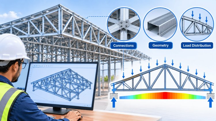
The selected truss configuration establishes the structural behavior of the entire roof system. Span, pitch, spacing, panel point geometry, heel conditions, and load paths must be coordinated early because they directly influence member sizing, connection design, fabrication complexity, and overall project cost.
Successful CFS truss design begins with choosing the right geometry. The correct truss configuration balances structural efficiency, fabrication simplicity, service integration, and long-term performance across the entire roof system.
Precise member detailing is the technical heart of CFS truss engineering. Each member — top chord, bottom chord, and web — has distinct structural roles, and their detailing must reflect the actual load paths, connection methods, and fabrication constraints of cold-formed steel construction.
Top chord members carry combined axial compression from gravity loads and bending from applied loads between panel points (purlins, roof deck, or direct sheathing). In CFS trusses, top chords are typically formed from C-sections (C-studs or C-joists) or tracks, with back-to-back or box configurations used for heavier loads. The sloped orientation of the top chord requires that shop drawings reflect the true cut angle at each heel and ridge node. Lateral buckling of the top chord compression flange must be restrained by continuous sheathing, roof purlins, or dedicated bracing elements spaced per AISI design requirements.
Bottom chords primarily carry tension under gravity loading and must be detailed for splice connections when chord length exceeds standard coil lengths. Under wind uplift conditions, bottom chords can experience reversal to compression — a critical check in highwind or hurricane-exposure design categories. Bottom chord bearing conditions at the truss heel must clearly define the bearing width, seat height, and any required bearing stiffeners. For attic storage configurations, bottom chords must also be designed for applied floor loads and deflection limits.
Web members transfer shear and stabilize the truss geometry under varied load combinations. In CFS trusses, webs are typically single C-sections or tracks connected to chord flanges or webs through gusset plates or direct screw connections. Web slenderness — the ratio of unbraced length to radius of gyration — governs compression web capacity and must be checked against AISI S100 column provisions. Detailed shop drawings must show web member lengths, end cut angles, and the precise screw pattern at each connection node.
Gusset plates in CFS trusses are punched or cut steel plates — typically 16 ga to 12 ga — that transfer load between converging members at panel points. Unlike timber connector plates, CFS gusset plates rely on screw fasteners (most commonly #10 or #12 self-drilling screws) arranged in defined patterns to achieve the required shear capacity. Connection design follows AISI S100 Chapter J provisions, with screw spacing, edge distance, and end distance strictly controlled.
Screw layout patterns must be dimensioned in full on shop drawings, including the number of screws per member face, row spacing, and minimum edge distances (typically 3× screw diameter from edge, 6× from adjacent fastener). Where multiple members stack at a node — such as a heel joint with top chord, bottom chord, and bearing stiffener — the connection sequence and gusset plate geometry must be carefully coordinated to avoid interference and ensure each member develops its full design force.
Screw type, diameter, and length specified per material stack-up
Minimum edge and end distances per AISI S100 Table J4
Bearing, tilting, and pull-out capacity verified for each connection
Gusset plate thickness and steel grade (Fy, Fu) documented
Eccentricity moments evaluated at non-concentric nodes
Block shear and net section checks at critical connections
Uplift anchor connections to bearing wall or structural header detailed
Simpson Strong-Tie or equivalent hold-down specifications crossreferenced
Member Detailing: Chords, Webs & Connections
Top Chord Members
Bottom Chord Members
Web Members
Gusset Plates & Screw Connection Arrangements
Connection Design Checklist
A correctly detailed CFS roof truss system must address not only the vertical gravity loads but also the full three-dimensional load path—including wind, seismic, thermal, and construction live loads. Load distribution and truss bracing are inseparable topics: without adequate bracing, even a perfectly designed truss can fail prematurely during construction or under service loads.
Address gravity, wind, seismic, and construction loads—and detail temporary, permanent, and diagonal bracing explicitly—to ensure stability during erection and throughout service.
Load Distribution, Bracing &
Structural StabilityLoad distribution and truss bracing are inseparable.
The final and most practically significant phase of cold-formed steel (CFS) truss detailing is the preparation of complete fabrication-ready shop drawings. These drawings translate engineering intent into manufacturing reality, providing fabricators, inspectors, and installers with the information required to build the truss system accurately, consistently, and without interpretation.
CFS trusses are typically manufactured using automated roll-forming equipment and CNC punch-and-cut systems that provide exceptional dimensional accuracy. Fabrication jigs and fixtures ensure that every truss is assembled to the intended geometry with minimal variation.
Quality control procedures should include member straightness verification, panel-point dimensional checks, screw installation audits, and confirmation that all fabrication tolerances comply with project requirements.
Shop drawing packages should include engineered calculations, bills of materials, quality assurance documentation, and any required deferred-submittal components. Design assumptions and governing standards should be clearly identified on drawing title blocks.
Compliance with applicable standards including AISI S100, AISI S202, ASCE 7, and the governing edition of the International Building Code must be documented before fabrication authorization is granted.
Establish accurate spans, pitches, panel-point locations, heel conditions, and framing geometry before performing member or connection design.
Gusset plates, screw patterns, edge distances, and eccentricity effects frequently govern truss performance more than member strength alone.
Temporary construction bracing is a life-safety requirement, while permanent bracing is essential for long-term structural performance.
Comprehensive shop drawings eliminate ambiguity, reduce RFIs, avoid fabrication errors, and minimize costly field corrections.
Successful cold-formed steel truss projects depend on a disciplined progression from geometry definition to connection engineering, bracing design, shop drawing preparation, and fabrication coordination. Complete documentation remains the single most effective risk-management tool available to engineers, fabricators, contractors, and owners. When design intent is communicated clearly through comprehensive shop drawings and supported by rigorous quality control processes, construction proceeds efficiently, compliance is simplified, and structural performance aligns with engineering expectations throughout the life of the building.
Shop Drawings, Fabrication & Key Takeaways
What Shop Drawings Must Include
Fabrication Coordination & Quality
Submittals & Code Compliance
Key Takeaways
Geometry First
Connections Are Critical
Brace Early & Permanently
Document Completely
Fabrication Approval Workflow
Final Professional Guidance
What's Your Reaction?