Light Gauge Steel Wall Panelization: From 3D Models to Factory Production
In today's fast-evolving construction landscape, light gauge steel (LGS) wall panelization has emerged as one of the most efficient methods for transforming complex architectural designs into precision-manufactured building components. By converting detailed 3D BIM models into fully documented, CNC-ready panel assemblies, construction teams can dramatically reduce on-site labor, minimize material waste, and accelerate project timelines — all while maintaining rigorous structural integrity. This presentation walks construction managers, structural engineers, prefab manufacturers, and BIM/CAD technicians through every critical phase of the LGS panelization workflow, from understanding the fundamental system logic to generating factory-ready fabrication data.
Understanding Panelized LGS Construction Systems
Panelized light gauge steel construction is a system in which the structural and non-structural walls of a building are designed, detailed, and fabricated as discrete, self-contained panels off-site — then shipped to the job site for rapid assembly. Each panel is a precisely engineered unit comprising cold-formed steel studs, top and bottom tracks, bridging, and all necessary bracing elements, pre-cut and pre-punched to exact specifications.
The foundation of any successful panelization project lies in a thorough understanding of two primary system categories:
Load-Bearing Wall Panels
These panels carry vertical gravity loads from floors, roofs, and upper stories, in addition to resisting lateral wind and seismic forces. Stud gauges are typically heavier (33 mil to 97 mil), and stud spacing is engineered per structural load calculations. Connections at panel ends, tops, and bases are detailed to transfer forces into the broader structural system. Every component — including stud size, track depth, and anchor bolt pattern — is specified by a licensed structural engineer and must conform to AISI S100 and AISI S240 standards.
Non-Load-Bearing Wall Panels
Designed primarily as partition or cladding systems, these panels must resist out-of-plane lateral loads (wind pressure on exterior façades) but are relieved of gravity load obligations. Lighter gauge studs (25 mil to 43 mil) are common, and deflection head track details allow the structure above to deflect without transferring load into the panel framing. Proper detailing of slip connections is critical to prevent distortion and cracking of attached finishes.
Why Early Classification Matters
Understanding which walls are load-bearing versus non-load-bearing at the outset of panelization is not merely a design formality — it determines stud sizing, connection details, and the entire downstream fabrication dataset. Early coordination between the structural engineer of record and the LGS detailer prevents costly rework and ensures compliance. Learn more about Consac's LGS design and detailing services to understand how this coordination is managed on live projects.
Labor Reduction
Typical on-site framing labor savings with panelized LGS vs. stick-built methods.
Max Stud Gauge
Heaviest cold-formed steel stud thickness used in load-bearing panelized systems.
Successful panelized LGS projects begin with a clear distinction between structural and non-structural walls. That single decision drives every subsequent detailing, engineering, fabrication, and installation workflow throughout the life of the project.
Panelized LGS construction succeeds when design intent, structural requirements, fabrication data, and installation sequencing are coordinated into one integrated system from the very beginning.
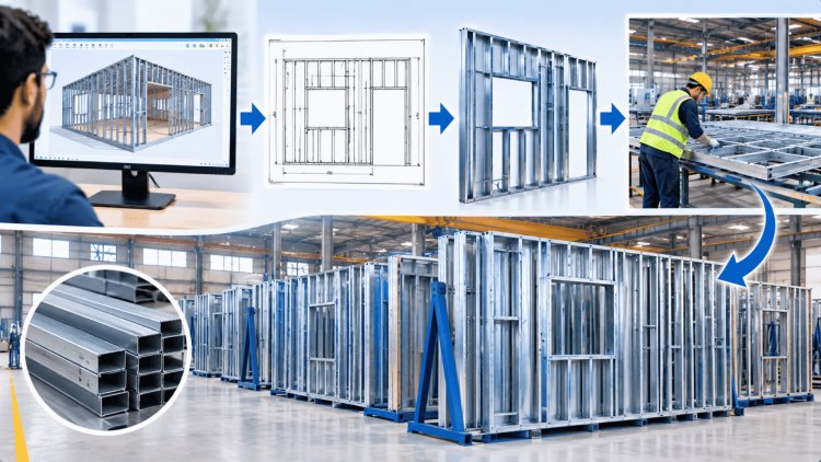
The transition from an architect's 3D model to a set of manufacturable LGS panels is a highly technical process that demands both engineering judgment and deep familiarity with fabrication constraints. It is not simply a matter of "slicing" the model — it requires deliberate panel layout decisions that balance structural logic, transportation limits, crane capacity, and erection sequence.
The architectural and structural BIM models are audited for dimensional accuracy, wall layer composition, opening locations, and clash resolution. Discrepancies between architectural intent and structural requirements are flagged and resolved before panelization begins. This coordination phase is critical — errors discovered here cost hours; errors discovered on the shop floor cost days.
Each wall line is segmented into individual panels based on maximum transportable dimensions (typically up to 12 ft tall and 40 ft long), structural break points, and erection logic. Panel joints are strategically located at corners, openings, and load-path transfer points. Panels are sized to allow efficient factory nesting on roll-forming or punch-press equipment.
Within each panel, stud spacing (typically 12", 16", or 24" o.c.) is laid out per engineering requirements. King studs and jack studs frame all openings; headers are sized per span and load. Bridging and blocking are incorporated. Utility knockouts, strap bracing locations, and sheathing attachment patterns are all detailed at this stage, producing a complete component map of every element within the panel.
Each panel receives a unique identifier linked to the project's panel schedule, elevation drawings, and assembly sequence. Shop drawings include panel elevation views, section cuts, connection details, and bill of materials (BOM). This documentation package is the contractual and production record that ties the factory output to the building design.
Explore Consac.com's LGS documentation capabilities to see how comprehensive shop drawing packages are structured for real projects.
The finalized panel models are exported as CNC-ready data files — typically in DSTV, MIS, or proprietary machine formats compatible with Framecad, Metsec, Howick, and similar roll-forming systems. Each file encodes stud length, punchout locations, dimple positions, and label data. The machine reads this file and automatically cuts, punches, and labels each component with zero manual measurement — dramatically reducing scrap and human error on the shop floor.
Breaking Architectural Models into Manufacturable Wall Panels
Model Audit & Coordination
Panel Layout & Segmentation
Stud, Track & Opening Arrangement
Panel Numbering & Assembly Documentation
CNC Fabrication Data Export
A well-detailed LGS panel is an engineering document as much as a fabrication instruction. Every element within the panel has a structural purpose, a dimensional tolerance, and a fabrication sequence. The following breakdown covers the core components that every LGS detailer must master.
Studs, tracks, bracing, openings, numbering, and documentation must work together as one coordinated panel system.
Stud, Track, Opening & Bracing:
The Anatomy of a PanelEvery element has a structural purpose, a tolerance, and a fabrication sequence.
The final and most impactful phase of the LGS panelization workflow is the generation of machine-readable fabrication data and the downstream efficiency gains it unlocks across the entire construction delivery chain. This is where rigorous digital detailing pays its greatest dividend.
Once panel shop drawings are reviewed, coordinated, and approved, the BIM model is processed through specialized LGS detailing software — such as Vertex BD, Tekla Structures, or proprietary platforms — to generate CNC output files. These files encode every fabrication instruction for each component in the panel:
Modern roll-forming systems (Framecad, Howick, Metsec, Scottsdale) can process CNC files and produce a complete panel's worth of labeled, punched, and cut components in under 15 minutes — a task that would require hours of manual layout and cutting using traditional stick-built methods. Discover how Consac's LGS fabrication drawing services integrate directly with leading roll-forming platforms to deliver zero-error CNC datasets.
Accurate panelization translates into measurable, compounding efficiency gains across every phase of the project lifecycle:
Pre-assembled panels arrive labeled and ready to crane-lift into position. On-site framing crews focus on connection and alignment rather than measuring, cutting, and laying out individual studs — typically reducing framing labor by 30–45%.
Clash resolution and opening coordination completed in the BIM environment eliminates the most common causes of on-site delays. Fewer requests for information (RFIs) mean faster decision cycles and uninterrupted installation flow.
Factory-produced components achieve dimensional tolerances impossible to replicate on a job site. Every panel is traceable to its shop drawing, CNC file, and QC inspection record — providing a complete audit trail for contract compliance and future building maintenance.
Accurate LGS panel design and steel framing panelization delivered through a rigorous BIM-to-fabrication workflow is the single most impactful investment a construction team can make to compress schedules, control costs, and ensure structural compliance. Ready to implement? Visit Consac.com to explore full-service LGS detailing and fabrication drawing solutions tailored to your project type and scale.
Generating CNC-Ready Fabrication Data & Maximizing On-Site Efficiency
From Model to Machine: CNC Data Generation
On-Site Efficiency Gains
Reduced Labor Hours
Fewer Delays & RFIs
Quality & Traceability
The true value of panelized LGS construction is unlocked when coordinated BIM data flows directly into CNC production, creating a seamless path from digital model to factory floor to jobsite installation with minimal waste, maximum accuracy, and predictable project outcomes.
What's Your Reaction?