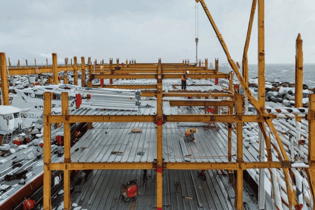
Floor Deck Detailing Near Stair Cores
One of the most geometrically complex and structurally critical interfaces in any multi-story commercial building is where the steel floor deck system meets the concrete stair core. This zone concentrates a unique combination of structural demands: slab edge conditions, core wall anchorage, moment transfers, fire-rating continuity, and construction sequencing constraints — all converging in a tight, congested plan area. Getting these details right is not a matter of preference; it is a prerequisite for building performance, life safety compliance, and constructability. This presentation provides a focused, technically precise guide to floor deck detailing at stair core interfaces — from framing geometry and pour stop selection through to final BIM coordination deliverables.

Understanding the Stair Core Interface Zone
Before detailing begins, the project team must understand that the stair core interface is not simply a slab termination point. It is a highly coordinated transition zone where structural framing, reinforced concrete walls, diaphragm behavior, architectural finishes, and vertical circulation requirements all intersect. Success depends on resolving these interactions before fabrication and construction begin.
Where Structure, Architecture,
And Access Systems Converge
The floor deck must terminate cleanly around the stair core while preserving structural performance, diaphragm continuity, architectural requirements, and egress functionality.
What the Stair Core Must Accomplish
Vertical Circulation
Provides safe and code-compliant movement between building levels.
Lateral Resistance
Acts as a primary shear wall system resisting wind and seismic forces.
Building Services
Accommodates egress systems and vertical mechanical routing paths.
Core Interface Coordination Path
Structural Considerations
Differential Deflection
The concrete core is significantly stiffer than the surrounding steel framing, requiring detailing that accommodates relative movement.
Diaphragm Force Transfer
Deck-to-core connections must transfer in-plane forces without inducing unintended wall moments.
Rib Orientation Effects
Deck ribs running parallel and perpendicular to the wall create very different termination and edge support details.
Composite Action Impacts
Effective slab width and composite behavior may be interrupted near the core perimeter.
Geometric Complexity Factors
Off-Grid Core Walls
Stair cores commonly intersect primary framing grids at angles, requiring custom-cut deck layouts and unique edge details.
Variable Slab Edge Conditions
Architectural requirements may require recessed, flush, or projecting slab edges at the core perimeter.
Landing Elevation Changes
Stair landings often create slab step-downs and step-ups that require careful framing transitions.
Re-Entrant Corners
Core wall intersections become stress concentration zones demanding reinforcement and carefully coordinated pour-stop details.
Typical Core Interface Challenges
Why BIM Coordination Matters Here
Because stair core geometry frequently departs from repetitive floor framing, BIM coordination becomes essential. Accurate modeling allows potential conflicts involving deck edges, stair landings, slab openings, wall geometry, framing interfaces, and architectural requirements to be identified before fabrication.
Stair Core Coordination Sequence
The Stair Core Interface Is a Structural Coordination Zone
Core-adjacent deck detailing must address more than slab termination. Differential deflection, diaphragm force transfer, deck orientation, landing elevations, geometric irregularities, and reinforcement requirements all converge at the stair core perimeter. A coordinated structural and BIM-driven approach is essential to delivering a constructible, conflict-free design.
The framing immediately adjacent to a stair core controls deck support, opening geometry, edge conditions, connections, and coordination requirements. Establish the strategy early and capture every interface accurately in the BIM model before detailing begins.
The primary steel member parallel to the core wall is typically a spandrel or header beam. It receives deck-edge loads and provides the attachment substrate for the pour stop. Its depth, web height, deck profile, and finished slab-soffit elevation must be coordinated as one assembly.
When the stair-core wall is skewed relative to the structural grid, some deck panels can no longer reach a primary grid beam. Infill framing must then be introduced to establish reliable panel support and should be explicitly identified in the framing plan and BIM model.
Moment-frame or lateral-system components near the stair core can occupy the same congested space as deck-edge framing, headers, closures, and connections. Kicker and knee-brace geometry should therefore be present in the coordinated model before deck panels and edge details are finalized.
A reliable stair-core framing strategy establishes the spandrel or header first, resolves all stair openings with properly assigned trimmers and headers, adds infill where the core does not align with the structural grid, and coordinates kicker or knee-brace geometry before deck detailing begins. These relationships should be captured in the BIM model so the final deck package reflects the complete structural interface rather than only the deck itself.
Framing Strategy at the Core Perimeter
Spandrel Beam or Header Beam Along Core Wall
Infill Framing for Non-Grid-Aligned Cores
Kicker or Knee Brace Coordination
Build the Model in the Right Order
The pour stop at the stair core interface is one of the most specification-sensitive elements in floor deck detailing — a concrete formwork edge, a fire-rated assembly component, a structural anchor, and a code-compliant barrier against runoff, all at once. Selecting the wrong type is a frequent cause of field rework.
Formed from galvanized steel with a fluted profile matching the deck rib pattern, the standard pour stop is welded or screwed to the spandrel beam flange.
Re-entrant corners — where two core walls meet at an inside corner — cannot be detailed with standard fluted pour stops alone. A fabricated plate or rigid angle must bridge the inside corner, fully welded on all sides to prevent concrete leakage.
Where the deck edge must be positively anchored to the concrete core wall — rather than simply bearing against it — cast-in anchors (headed studs, threaded inserts, or embedded plates) must be coordinated with the core wall rebar layout.
The stair core interface asks a single pour stop assembly to serve as formwork, fire barrier, structural anchor, and code-compliant edge simultaneously. Show every notch, closure, corner plate, and cast-in anchor explicitly on the drawings — and verify the assembly against its tested fire rating before concrete is placed.
Pour Stop and Deck Edge Details
Fluted Pour Stop (Standard)
Rigid Angle or Plate at Re-entrant Corners
Cast-In Deck Anchorage to Core Wall
Spandrel or header beams along the core wall act as chords or collectors, designed for combined gravity and axial loads. Their connections must transfer diaphragm shear into the core wall. In high-force zones, reinforced concrete drag struts may supplement or replace steel chords, requiring careful deck-to-slab coordination.
Force transfer requires positively designed connections, not incidental bearing. Common anchorage methods include:
Details must clearly show the load path from deck rib, through pour stop or closure angle, into connection hardware, and finally into the core wall.
Diaphragm continuity at core walls is a critical structural link. Explicit detailing, BIM coordination, and positively designed anchorage ensure lateral forces are reliably transferred, preventing hidden weaknesses in the building’s seismic and wind load path.
Diaphragm Continuity and Load Path at Core Walls
Diaphragm Chord and Collector Elements
Diaphragm-to-Core Wall Anchorage
Load Path Summary
Key Insight
Stair core interfaces are among the highest-density clash zones in any building model. Concrete walls, embedded hardware, rebar cages, landing framing, stair systems, mechanical chases, and composite deck assemblies all compete for the same limited space. A disciplined BIM coordination workflow is essential for eliminating costly conflicts before fabrication and construction begin.
The complexity of the stair core exceeds what traditional 2D detailing can reliably coordinate. Accurate modeling, clash detection, and issue resolution are required to prevent fabrication delays, field modifications, and schedule impacts.
The reinforced concrete core wall model should become the fixed reference geometry for all subsequent coordination. Wall faces, embedded plates, reinforcement envelopes, anchors, sleeves, blockouts, and mechanical penetrations must be established before steel framing or deck geometry is finalized. The wall model becomes the baseline against which all future clash detection is performed.
Trimmers, headers, spandrel members, seat angles, coping geometry, connection components, pour stops, and closure strips should all be modeled to full LOD 350 accuracy. Edge condition components must participate in clash detection as structural objects rather than finishing elements.
Stair-core-adjacent deck panels should be modeled with accurate cut geometry reflecting actual wall interfaces. Angular cuts, skewed wall intersections, irregular openings, and custom edge conditions must be represented exactly as intended for fabrication and erection.
Non-standard deck panels located around stair cores should be clearly identified in the BIM model and shop drawings for fabrication review and erection sequencing.
Stair core areas routinely generate a disproportionate amount of project conflicts. Dedicated clash review sessions should be performed before releasing any fabrication package to ensure all structural, concrete, mechanical, and rebar conflicts have been resolved.
BIM Coordination and Detailing Deliverables
BIM Coordination Is Not Optional
At the Stair Core InterfaceCore Coordination Workflow
Model Core Wall Geometry First
Required Verification
Model Infill Framing and Edge Conditions
Deck Panel Layout and Cut Geometry
Custom Deck Panel Identification
Clash Detection and Issue Resolution
What's Your Reaction?