Steel Deck Sheet Layout Planning for Large Buildings
Effective steel deck sheet layout planning is one of the most consequential—and most frequently underestimated—steps in the structural coordination of large commercial and industrial buildings. When deck sheets are positioned, oriented, and sequenced without a disciplined layout strategy, the downstream effects ripple through fabrication, erection schedules, weld patterns, and inspector sign-offs. Done well, layout planning reduces material waste, accelerates erection crews, and creates a predictable coordination environment for structural engineers, detailers, and project managers alike.
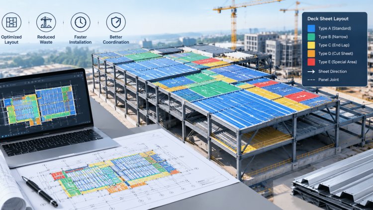
Core Layout Principles: Orientation, Span Direction & Bay Logic
Every steel deck layout begins with a fundamental structural decision: which direction do the sheets span? Deck sheets are designed to span perpendicular to the supporting framing members—joists or beams—and this orientation must be established before a single sheet boundary is drawn. For composite floor decks, the flute direction also determines where shear studs can be welded and how concrete is placed, making orientation a multi-discipline decision.
Span Direction Rules
Bay-by-Bay Layout Logic
Large buildings are most efficiently detailed by treating each structural bay as a discrete layout zone. Within each bay, the detailer establishes sheet length, sidelap quantity, endlap location (if any), and closure conditions at edges and openings.
Endlaps—where one sheet overlaps another along the span direction— should be staggered between adjacent bays to prevent concentrated load transfer and improve composite behavior. Sidelaps connect sheets parallel to the span and must be fastened per the SDI deck specification requirements.
For buildings with repetitive bays, a master bay layout can be developed and replicated across the floor plate, dramatically reducing detailing time and enabling pattern checking during erection. Consult Consac's Joist and Deck coordination guides for how bay layout integrates with joist spacing decisions.
Sheet Length
Standard lengths run 6 ft to 40 ft. Longer sheets reduce endlap count but increase erection crane picks and handling risk.
Endlap Location
Must occur over a structural support. Minimum 2" endlap. Never locate endlap in mid-span— this is a critical detailing error.
Sidelap Fastening
Button punch, screws, or welds— spacing determined by diaphragm design. Document fastener type and pattern explicitly on layout drawings.
Edge Conditions
Perimeter angles, pour stops, and closure plates must be coordinated with deck layout so no sheet overhangs unsupported edges without a back-up angle.
Successful deck detailing starts with orientation. Once flute direction, span logic, and bay repetition are established correctly, sheet lengths, endlaps, sidelaps, and edge conditions can be coordinated efficiently across the entire floor plate.
Establish span direction first, organize layouts bay-by-bay, and coordinate every endlap, sidelap, and edge condition before drawings reach the field.
While repetitive rectangular bays represent the ideal layout condition, most large commercial and industrial buildings introduce geometric complexity: skewed column lines, curved perimeters, offset bays, and large floor openings for stairs, elevators, mechanical shafts, and atriums. These conditions require deliberate layout strategies that go beyond simple sheet replication.
Openings larger than a single flute width require reinforced framing—typically structural steel header beams framing around the opening perimeter. The deck layout must ensure that all sheets adjacent to the opening bear on these headers with the minimum required bearing. Sheet cuts at opening edges must be dimensioned from the nearest column line or grid reference, not from the opening itself, to maintain layout accuracy. The deck layout drawing should show opening dimensions, elevation at deck top, and all supplemental framing members.
Trim angles and pour stops at opening edges must be coordinated with the deck layout so they are shown on the same drawing rather than referenced separately—a common coordination gap that leads to field conflicts. For complex deck opening behavior, see Consac's Steel Joist Detailing resources for joist header framing details.
Set primary and reference lines for bays
Log skewed lines, cutouts, and offsets
Create cut and infill schedules for fabrication
Managing Irregular Grids, Skewed Bays & Large Openings
Large Floor Openings
Establish Grid
Document Irregularities
Produce Cut Sheets
On large buildings, steel deck is rarely installed in a single continuous operation. Phased erection—driven by structural steel sequencing, concrete pour scheduling, and crane access—means that the deck layout plan must also function as an erection sequence document. Deck layout drawings that ignore phasing create coordination failures: mismatched sheet orientations at phase boundaries, unsupported edge conditions during intermediate construction stages, and conflicts with MEP rough-in that follows closely behind the deck crew.
Color-code each phase on the layout plan and cross-reference it to the milestone date by which that phase’s deck must be installed and accepted before concrete can be poured. This elevates the deck layout document from a shop drawing to a project management tool. For integrated joist-and-deck project coordination frameworks, explore Consac’s Joist and Deck coordination library.
Phased Erection Sequencing &
Multi-Trade CoordinationVersion-control the deck layout and tie it to the master erection schedule.
The deck layout drawing is the single most referenced document in a steel deck package. It must communicate sheet orientation, endlap and sidelap locations, fastening patterns, opening reinforcement, edge conditions, material specifications, and erection sequencing information in a format that field crews can interpret quickly under real construction conditions.
Verify panel bearing lengths, confirm endlaps occur directly over supports, review sidelap fastening consistency, validate opening locations, and ensure all deck zones comply with design requirements before advancing to coordination review.
Cross-check the layout against the latest structural steel erection documents, verify framing revisions, confirm joist updates, and ensure no issued structural changes invalidate completed deck detailing work.
Deck layout submittals should be accompanied by a material takeoff organized by deck type and construction phase, a fastening schedule coordinated with diaphragm requirements, and a documented list of unresolved coordination issues requiring Engineer of Record review.
RFIs involving field cuts, opening reinforcement, diaphragm transitions, phase-boundary conditions, and support modifications should be logged with target response dates and tracked through closure before the affected erection phase begins. Delayed responses on deck coordination issues remain one of the most common causes of field stop-work conditions.
Required bearing length at sheet supports per SDI standards.
Technical verification followed by formal coordination review.
Standard practical limit before erection handling complexity increases.
Required overlap over supports and must be documented explicitly.
Clean submittal packages are the result of disciplined drawing standards, structured quality control, and proactive coordination management. Drawings with complete span information, explicit fastening schedules, detailed edge conditions, coordinated openings, and verified support relationships consistently generate fewer RFIs, move through approval cycles faster, and reduce downstream field disruptions. The hours invested in pre-submittal review are recovered many times over during fabrication, erection, and final construction execution.
Drawing Standards, Quality Control & Submission Best Practices
Drawing Content Checklist
Structural Information
Documentation Controls
Two-Stage Quality Control Process
Technical Review
Coordination Review
Submission & RFI Management
Final Submission Principle
What's Your Reaction?