Roof Deck Detailing for Sloped Framing Areas
A technical deep-dive into the geometric, structural, and documentation challenges unique to sloped roof deck assemblies — from variable joist seat elevations and tapered bearing conditions to BIM modeling strategies that keep fabrication drawings clean and coordinated.
Why Sloped Roof Framing Demands a Different Detailing Approach
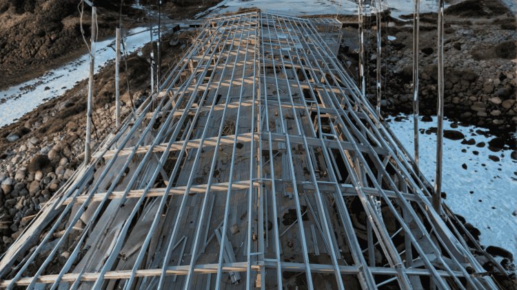
Flat roof detailing relies on repetition. Sloped roof detailing relies on geometry. As roof slopes increase and roof forms become more complex, every connection, support condition, panel cut, and coordination point must be evaluated within a three-dimensional framework. What works as a standard detail on a flat roof often becomes inadequate when applied to ridges, valleys, hips, and varying roof elevations.
Geometry Drives Everything
The Core Challenge
On a flat roof, geometry remains constant throughout the structure. On a sloped roof, every bay may have unique seat elevations, support conditions, panel lengths, closure details, and framing intersections. The design challenge shifts from repetition to coordination.
Uniform Geometry
• Repetitive deck spans
• Standard closures
• Consistent bearing lengths
• Predictable diaphragm behavior
Variable Geometry
• Compound deck cuts
• Custom edge conditions
• Unique bearing checks
• Interrupted load paths
Structural Geometry Becomes the Primary Design Driver
As roof slopes change, support elevations change with them. Joist seat locations that would typically repeat on a flat roof often require individual elevation verification in sloped roof systems.
Sloped framing turns a “typical” seat and deck termination into a location-specific geometry problem. Every support point must be checked for elevation, bearing, fit-up, and load transfer.
Set the structural datum, girder slope, joist lines, and top-of-steel elevations.
Calculate support elevation at every joist or joist-girder bearing point.
Size the seat or sloped bearing so the joist reaction has adequate contact and alignment.
Check gaps, bearing, top-chord clearance, deck elevation, connections, and erection tolerances.
When a steel joist is installed on a slope, the standard flat-roof seat may not provide the required depth or geometry. SJI guidance recognizes increased seat-depth requirements for sloped joists, and manufacturers provide tables for the applicable slope and joist type. [670][673][684]
Standard seat dimensions are starting points, not a substitute for the actual slope, support, joist extension, reaction, and erection condition.
Metal deck is manufactured as a flat, rectangular product. The deck follows the roof framing slope in its span direction, while ribs and end geometry still have to fit the actual support line.
At valleys, hips, skewed beams, and non-perpendicular supports, the panel end may need a field cut to maintain the required bearing width across the support.
Measure the remaining bearing at the acute and obtuse ends after the cut. Do not assume the original rectangular panel bearing remains available.
Calculate the local top-of-steel and joist underside elevations at each support.
Verify required clear bearing, seat depth, contact, and reaction alignment.
Check deck cuts, gaps, rib alignment, closure fit, and erection tolerances.
Confirm joist reactions, deck support, diaphragm transfer, and local reinforcement.
Small elevation differences may be accommodated in some systems, but shimming cannot replace adequate bearing, correct seat depth, stable load transfer, or a coordinated deck support.
Calculate every support locally, size seats for the actual slope, and verify deck bearing after every skewed or field cut. A sloped roof deck is complete only when joists, supports, panels, fasteners, and drainage geometry share the same elevation model and the same load path.
Seat Elevations, Panel Fit-Up, and Bearing
Variable Seat Height Calculation
Bearing Depth Changes with Slope
Do Not Rely on a Nominal Seat
Verify the required clear bearing and seat depth for the joist series.
Confirm the larger bearing and extension requirements where applicable.Deck Panel Fit-Up on Sloped Supports
Flat Product, Sloped System
Skew Requires a Cut
Bearing After Cutting
Geometry Checks at Every Sloped Support
Recommended Detailing Workflow
Sloped Framing Detail Checklist
Do Not Assume Field Shimming Fixes the Geometry
The Sloped-Framing Principle
Each edge condition in a sloped roof assembly is a unique structural and weatherproofing interface. Unlike flat decks, sloped decks produce geometry that changes along ridges, valleys, and rake edges. These closure details are frequent problem areas in shop drawing review and field coordination.
At a ridge, opposing deck runs terminate at the roof’s high point. A ridge closure caps open flutes, prevents infiltration, and maintains diaphragm continuity. Ridge framing must provide bearing for both runs, with SDI recommending 1.5 inches minimum. When flange width is insufficient, ridge plates or header angles extend the bearing surface. Sidelap fasteners within 12 inches of the ridge are mandatory.
Valleys converge slopes at a low point. Deck panels must terminate cleanly without ponding traps or diaphragm breaks. Valley members must accommodate both slopes with compliant bearing. Closure channels prevent debris and direct water to drains. Engineers must verify valley members carry combined tributary loads, including snow drift per ASCE 7 provisions.
At the eave, deck terminates at the slope’s low end over perimeter support. The eave angle provides bearing and fascia attachment, set to match slope (not level). This affects anchor bolt layouts, fascia alignment, and gutter details. Rake edges require rake angles or trims parallel to slope, with panels cut flush or slightly past the rake member. Cut edges must be cleaned and treated to prevent corrosion.
Ridge, valley, eave, and rake closures are critical interfaces where geometry, structure, and waterproofing converge. Proper detailing ensures diaphragm continuity, drainage performance, and long-term durability of sloped roof assemblies.
Ridge, Valley, Eave, and Rake Edge Details
Ridge Line Condition
Valley Framing Condition
Eave and Rake Edge Conditions
Key Insight
Sloped roof projects often appear coordinated in 3D views while still containing significant geometric errors that only emerge during fabrication or erection. Incorrect slope assignment, inaccurate seat elevations, simplified panel geometry, and improperly modeled closure components are among the most common causes of RFIs and field corrections. Production-grade BIM workflows must model actual constructible geometry rather than idealized design intent.
A visually clean BIM model can still contain incorrect seat elevations, bearing assumptions, closure geometry, and panel layouts. The objective is not visual accuracy alone but construction accuracy.
Every joist should be modeled using actual support elevations. Standardized seat assumptions frequently fail on sloped roofs because high-side and low-side seats are rarely identical.
Utilize joist end-condition parameters for seat height control.
Model true support elevations and fabrication conditions.
Use custom parameters or adaptive components for seat variation.
Ridge closures, valley closures, rake trims, and eave angles should be modeled as individual components with correct slope and elevation assignments. Annotation-only approaches frequently create false clash-free conditions and allow roofing and MEP conflicts to remain hidden until construction.
BIM Modeling Strategies for Sloped Roof Deck Assemblies
The Hidden Coordination Risk
Joist Seat Modeling Must Reflect Reality
Tekla Structures
SDS/2
Revit
Closure Elements Must Be Real Geometry
Sloped roof deck detailing rewards geometry-first discipline. Use this checklist before issuing coordinated BIM models, structural drawings, or deck shop drawings.
Do not apply one seat height across a sloped bay. Calculate the local top-of-steel elevation and required seat geometry at each joist support.
Ridge, valley, eave, and rake conditions each deserve a discrete detail rather than a general note or field interpretation.
Use actual top-of-steel elevations and separate planes for each roof facet. Model skewed panel cuts and sloped closures as real geometry.
□ Two-sided deck bearing checked. □ Skewed cuts modeled. □ Edge support detailed. □ Cut edge supported. Review seat schedule, sloped bearing, reactions, extensions, and support elevations.
Review profile, bearing, panel cuts, closures, end-zone fastening, and field-cut limits.
Review insulation build-up, membrane transitions, closures, drainage, flashing, and installation access.
General notes cannot carry unresolved geometry.
Geometry-first detailing is the best quality-control system for sloped roof decks. Calculate seat heights per support, detail every closure, build the BIM model from accurate sloped planes, and issue the coordination package before the design is locked. The result is a roof deck that can be fabricated, erected, waterproofed, inspected, and defended.
Key Takeaways and Documentation Checklist
Calculate Seat Heights per Joist
Detail Every Closure
Build on Accurate Sloped Planes
Seat and Bearing QC Checklist
Ridge, Valley, Eave, and Rake Checklist
□ Ridge closure shown.
□ End fastening documented.
□ Valley support verified.
□ Snow-drift effects reviewed where applicable.
□ Closure and fascia coordinated.
□ Membrane and air-barrier continuity checked.
□ Trim and closure shown.
□ Connection and flashing access verified.
BIM Documentation Checklist
Issue the Coordination Package Early
Joist Fabricator
Deck Supplier
Roofing Contractor
Standards and Reference Map
Diaphragm design, attachment, and capacity guidance.
Joist seats, bearing, sloped ends, and special joist conditions.
Structural steel design, framing, and connection coordination.
Applicable rain and snow-drift load provisions.
Architectural sheet-metal, ridge, valley, eave, and rake practices.If It Is Not Scheduled, Modeled, or Detailed, It Is Not Coordinated
The Documentation Principle
What's Your Reaction?