Floor Deck Detailing for Mixed- Use Developments
Mixed-use structures demand a level of floor deck detailing rigor that single occupancy buildings rarely require. When residential units stack above retail podiums, parking garages, and commercial office floors — each governed by distinct load regimes, vibration tolerances, span requirements, and fire-rating criteria — the detailing engineer must reconcile competing performance demands within a single structural bay. This presentation consolidates critical detailing considerations specific to mixed-use floor decks: from floor-to-floor height management and composite vs. non-composite deck selection, to transfer slab transitions, expansion joint coordination, and BIM modeling discipline. Whether you're producing construction documents or coordinating a 3D model for a multi-discipline project, these principles form the technical backbone of accurate, constructible floor deck details.
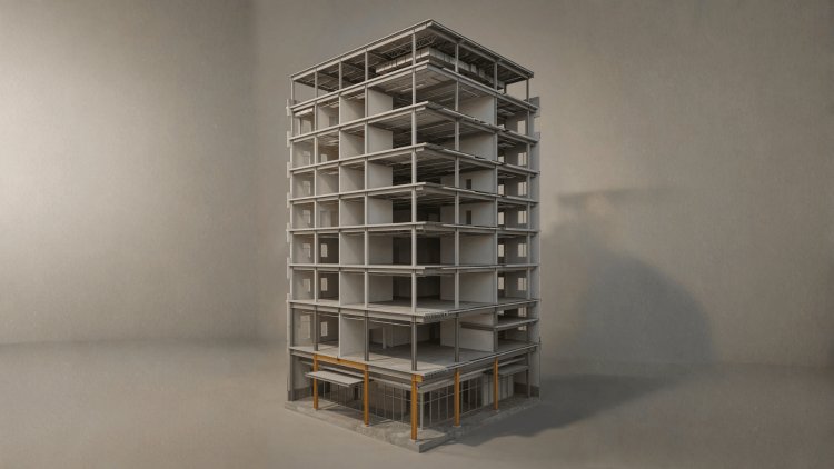
Why Mixed-Use Demands a Different Detailing Approach
Mixed-use developments challenge conventional floor deck detailing because no single occupancy governs the entire structure. Residential apartments, offices, retail podiums, parking structures, and amenity spaces often coexist within the same building. Each occupancy introduces its own structural demands, vibration criteria, fire-rating requirements, acoustic expectations, and long-term performance considerations. Successful detailing requires a coordinated approach capable of addressing all these requirements simultaneously.
One Building. Multiple Structural Languages.
The floor deck detail must successfully accommodate different occupancy requirements, performance targets, and code obligations while maintaining a coordinated structural system.
Occupancy-Driven Load Variability
A single mixed-use floor plate may transition between residential, office, retail, and support spaces within the same structural level. These changes often require localized slab thickness adjustments, different deck profiles, varying beam sizes, modified stud layouts, and careful control of differential deflection between adjacent occupancy zones.
Vibration Performance Divergence
Long-span systems that perform well in office environments may fail to satisfy residential vibration expectations. Residential occupancies typically require tighter walking excitation criteria and greater occupant comfort, often forcing redesign of deck profiles, concrete thicknesses, beam spacing, and framing layouts where occupancy transitions occur.
Why Transitions Must Be Flagged
Fire-Rating Transitions
When residential occupancies are located above business, retail, or mixed commercial spaces, floor assemblies typically must satisfy more demanding fire-resistance requirements. Deck gauge, slab thickness, concrete cover, and fireproofing details must be carefully coordinated at occupancy boundaries.
Acoustic & Vibration Isolation
Mixed-use buildings frequently separate apartments from retail tenants, restaurants, offices, fitness areas, or mechanical rooms. Structure-borne vibration and airborne noise become critical design concerns that often require floor-ceiling assemblies specifically engineered to achieve desired STC and IIC ratings.
The choice between composite and non-composite deck should be made zone by zone in mixed-use buildings. The decision affects structural behavior, detailing requirements, construction sequencing, MEP coordination, and the information carried into the BIM model.
Mixed-use occupancy transitions should not rely only on visual differences in the model. Each deck zone should carry structured parameters that preserve the actual structural and detailing intent for analysis exports, quantity takeoffs, coordination, and shop drawing production.
Evaluate spans, loads, occupancy, MEP needs, and structural behavior for each floor zone.
Record profile, gauge, slab thickness, reinforcement, attachment, and composite status on drawings.
Maintain distinct model parameters so analysis, quantity takeoff, and detailing remain accurate across occupancy transitions.
Composite and non-composite deck should be treated as distinct structural systems within a mixed-use floor plate. The selection should be documented at the zone level, coordinated with the framing and MEP layouts, and represented through explicit BIM parameters so that the structural model, shop drawings, quantities, and field installation all reflect the same design intent.
Composite vs. Non-Composite Deck Selection
BY ZONEWhich System Fits the Floor Zone?
Keep Composite and Non-Composite Zones Distinct in BIM
Selection → Documentation → Coordination
Select by Zone
Document Explicitly
Coordinate in BIM
Podium transfer slabs are typically post-tensioned concrete ranging from 18″ to 48″ thick. Steel floor deck above must account for long-term camber and creep. Detailers must coordinate shim heights at steel column bases and document short- and long-term deflections in construction notes, reconciling them with partitions, storefronts, and mechanical clearances.
When tower columns do not align with podium columns, moment transfer through the slab creates concentrated demands. Deck around these conditions requires thickening, supplemental reinforcement, or flat plate zones. BIM models must represent these regions explicitly for accurate analysis, takeoff, and coordination with mechanical soffits.
At podium tops, steel base plates, anchor bolts, and grout pads must be detailed to accommodate tolerances between concrete and steel. Floor deck requires pour stops, closure angles, and edge reinforcement bridging the transition. Expansion provisions must be evaluated independently from typical floor joints.
Transfer slabs at podium levels are the nexus of architectural ambition and structural precision. Coordinating slab geometry, column offsets, and steel-to-concrete interfaces ensures stability, accuracy, and seamless integration across mixed-use developments.
Transfer Slabs, Setbacks & Discontinuous Framing
Transfer Slab Geometry & Thickness
Column Setback & Offset Details
Steel-to-Concrete Interface Details
Key Insight
Expansion joint detailing is one of the most coordination-intensive aspects of mixed-use floor construction. The responsibility extends far beyond identifying a joint location. Structural behavior, deck termination, fire protection, waterproofing, architectural finishes, and MEP systems all converge at these interfaces. Accurate detailing at the design stage prevents costly field modifications and protects long-term building performance.
Structural expansion joints become necessary at seismic separations, podium-to-tower interfaces, and long uninterrupted floor plates generally exceeding 200 to 250 feet. At these locations, floor deck systems must terminate cleanly rather than continue through the joint, allowing each structural segment to move independently.
Full-depth pour stop angles or plates are required at both sides of the joint. These components must resist wet concrete loading and deck reactions without excessive deflection during slab placement.
Seismic and expansion-joint covers must accommodate anticipated building movement, typically ranging from ±1 inch to ±3 inches in multi-story mixed-use construction.
Expansion joints crossing fire-rated floors require UL-listed intumescent or ceramic-fiber systems. These assemblies must be detailed explicitly within the structural documents rather than delegated to field interpretation.
Parking structures and podium roofs require waterproofing membranes that remain continuous across expansion joints while avoiding ridges that may collect water or interfere with vehicle traffic.
Even where structural expansion joints are unnecessary, composite slabs remain susceptible to shrinkage cracking. Control joints help direct cracking to predictable locations while protecting long-term floor appearance and performance.
L-angle or hat-section closure attached to perimeter framing to contain wet concrete and create a clean slab edge.
Prevents deck edge uplift during concrete placement where deck spans perpendicular to the spandrel member.
Provides attachment support for cladding anchors, guardrails, façade systems, and exterior wall components.
Slab edge plates and perimeter attachment details must be represented in both structural and architectural BIM models to ensure complete coordination of cladding systems, guardrails, embeds, and facade support components.
Re-entrant corners at floor setbacks are common crack initiation locations. Structural notes should specify diagonal reinforcement consisting of a minimum of two #5 bars installed at 45° at every re-entrant slab corner to control crack formation and improve slab durability.
Successful mixed-use floor deck detailing requires coordinated treatment of expansion joints, concrete control joints, slab edge conditions, waterproofing systems, fire-resistance assemblies, and architectural interfaces. By explicitly detailing these components rather than leaving them to field interpretation, project teams reduce construction conflicts, improve long-term performance, and protect the integrity of the entire building system.
Expansion Joints, Control Joints
& Edge ConditionsStructural Expansion Joints
Expansion Joint Assembly Components
Deck Termination
Joint Cover Assemblies
Fire-Rated Assemblies
Waterproofing Continuity
Control Joints in Concrete Topping
Coordination Requirements
Edge Condition Types & Specification
Closure Angle / Pour Stop
Shear Tab / Spandrel Clip
Slab Edge Plate
BIM Coordination Requirement
Critical Structural Note
Joint Detailing Workflow
Joint Detailing Is About More Than Movement
What's Your Reaction?