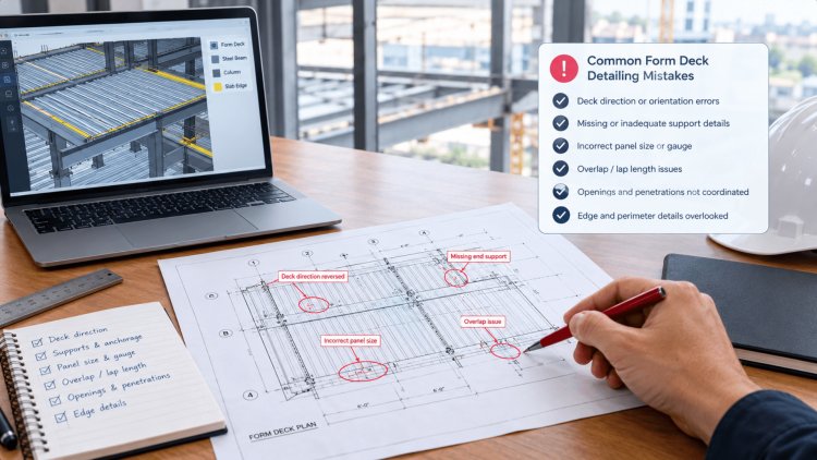
Form Deck Detailing Fundamentals
Span & Bearing: The Most Costly Silent Errors
Span and bearing conditions are where the most expensive field surprises originate. Engineers and detailers often operate from different assumption sets — and neither writes them down explicitly on the drawing.
Common Span Errors
Unspecified span condition: Form deck can be detailed as single-span, two-span, or three-span continuous. If your notes don't call this out explicitly, the erector defaults to single-span — which may be under-designed for your actual loads.
Overlooking panel direction: The span direction of the flute must be shown clearly on the plan. Reversing it changes structural behavior entirely and can invalidate your load tables.
Omitting intermediate supports: Temporary shoring assumptions during concrete pour are rarely shown on form deck drawings but are critical for wet concrete deflection checks.
Ignoring re-entrant corners: At setbacks and floor step-downs, the effective span changes — details must reflect this, not rely on a uniform span note.
Bearing Length & Edge Conditions
Minimum bearing not called out: SDI standards require a minimum of 1.5 inches on steel and 3 inches on concrete or masonry. This must appear in your general notes and be shown at atypical conditions.
Missing edge angle callouts: Slab edges without a specified pour stop or edge angle are among the top RFI generators in form deck packages. Every free slab edge needs a detail.
No closure plate at end laps: Open flute ends at walls and beams allow concrete to flow into unintended cavities. Closure plates must be shown and specified by gauge.
Inconsistent bearing on deep beams: When beams are significantly deeper than adjacent framing, the deck elevation and bearing must be reconciled in section detail — not assumed.
Pre-Submittal Verification
Before submittal, walk every perimeter condition and re-entrant corner in your model or plan set. Cross-reference your deck detailing standards to confirm bearing callouts are complete and consistent.
Most costly deck failures are not caused by complex engineering problems. They begin with undocumented span assumptions and incomplete bearing details.
Concrete Thickness, Gauge & Load Notation Mistakes
The structural properties of a form deck system are inseparable from the concrete topping thickness and the deck gauge. When these values are inconsistently noted — or not noted at all — the fabricator, contractor, and inspector are all working from different assumptions. These discrepancies don't usually surface until the pour is underway or an inspector flags a discrepancy.
Concrete Thickness Callouts
Total slab thickness and concrete above the flute (topping thickness) are two different dimensions — and both must be explicitly shown. Relying on a single "T.S. = 3.5 inches" note is insufficient. Your section details should show the deck profile with dimensional callouts for overall thickness AND the structural concrete depth above the flute. Inconsistencies between plan notes and section details are a leading cause of RFIs and must be reconciled before submittal.
Deck Gauge Specification
Gauge must be specified per zone, not globally. It is common practice to vary gauge across a floor plate — heavier gauge at longer spans or higher live load areas, lighter gauge at short spans. A single general note saying "20 GA unless noted" is frequently misread. Zone-by-zone gauge callouts on the plan, supported by a deck schedule, provide the clarity installers and inspectors need. Always confirm your selected gauge against the SDI load tables for your actual span and loading combination.
Construction vs. Live Load Notation
Form deck drawings must clearly distinguish between constructionstage loads (wet concrete, construction live load) and in-service loads. If your drawing notes only reference the in-service design load, the erector may not know the deck was checked for the pour sequence. Both load cases should appear in the drawing notes, with a reference to the controlling SDI or AISC criteria. This is especially important on long spans where wet concrete deflection governs.
Composite vs. Non-Composite Confusion
Form deck is non-composite by definition — it provides a forming surface only. If shear studs appear on your framing plan, the composite action is between the concrete and the beam, not the deck. However, drawing notes that reference composite deck properties, or that mistakenly call out embossed form deck, create dangerous confusion. Confirm your deck designation (e.g., 1.5VLI vs. 1.5VL) is consistent with non-composite intent throughout the package. Learn more about joist and deck coordination to avoid cross-discipline notation conflicts.
Always reconcile thickness callouts between the architectural reflected ceiling plan, the structural floor plan, and section details before submittal. Discrepancies between disciplines are the single most common source of form deck RFIs.
Form Deck Detailing
Openings, Attachments &
Coordination Gaps
Openings through form deck and the attachment pattern to supporting steel are two areas where detailing packages are routinely incomplete. Structural engineers often address large openings with framing plans but leave small-to-medium openings to the contractor—a practice that creates field liability. Attachment details are equally prone to omission: fastener type, spacing, and side-lap stitching are structural decisions, not field judgment calls.
What gets missed
Opening Details
Unframed openings under 12 inches
Many structural packages explicitly exclude openings below a threshold size from the structural drawings, delegating them to the contractor. However, even small openings can affect the deck’s ability to function as a diaphragm. Establish a clear policy and document it in your general notes.
No reinforcing callout at slab edges
Openings require trimmer angles or supplemental reinforcing at the cut edges of the deck. These must be shown in section detail—not left to the erector’s discretion.
Missing pour stop at block-out perimeters
Every opening in a formed slab requires a pour stop or header angle at its perimeter. These are frequently omitted from form deck drawings and assumed to be in the architectural or MEP set.
Stair and elevator shaft edges
These large openings often have complex geometry. Confirm that your deck plan shows framing, edge angles, and any camber or slope transitions in full detail—not a single dashed rectangle.
02
Attachment & Side-Lap Requirements
Puddle welds, powder-actuated fasteners (PAF), and self-drilling screws have different structural values. Specify the attachment type and verify it against your diaphragm design. Diaphragm capacity is directly tied to fastener spacing at sheet edges and at intermediate supports.
Fastener type not specified: identify welds, PAF, or self-drilling screws.
Fastener spacing omitted: show 36/4, 36/7, or equivalent SDI-recognized patterns.
Side-lap stitching not shown: screws or button punches must appear on the drawing, not only in a specification section.
For complex floor plates with multiple opening conditions, a dedicated form deck plan separate from the structural framing plan dramatically reduces coordination errors. Cross-reference your steel joist detailing standards to ensure deck attachment at joist seats is explicitly addressed, particularly at end conditions and at re-entrant corners where diaphragm loads concentrate.
Detailing standard
Openings and attachment patterns are structural decisions—not field judgment calls.
Document opening policy, reinforcing, pour stops, fastener type, spacing, and side-lap stitching directly in the form deck drawing set.
Form Deck Quality Assurance
Pre-Submittal QC Checklist & Final Review Protocol
A systematic pre-submittal QC review is not a final read-through—it is a structured cross-check against known failure modes. The categories below represent the minimum scope of a defensible QC review for form deck submittal packages. Complete each category before the drawing set is stamped and transmitted.
01
Plan Completeness
- Deck type and gage shown per zone.
- Span direction arrows provided in every bay.
- All edges labeled with pour stop or angle type.
- All openings fully located and dimensioned.
- Composite versus non-composite intent clearly identified.
02
Notes & Specifications
- Concrete thickness shown for total slab depth and depth above flute.
- Minimum bearing lengths stated for both steel and concrete supports.
- Construction and in-service loading requirements referenced.
- Fastener types and spacing match SDI diaphragm requirements.
- Side-lap stitching spacing specified.
03
Detail Sufficiency
- Section provided for every unique slab edge condition.
- Closure plates shown at flute ends adjacent to walls and beams.
- Supplemental framing detailed at all openings.
- Bearing verified at step-downs and framing transitions.
- Shoring requirements indicated where wet concrete loading governs.
04
Cross-Discipline Check
- Slab thickness coordinated with architectural and MEP drawings.
- Deck openings reconciled with all block-outs and penetrations.
- Joist seat elevations verified against deck bearing conditions.
- Diaphragm zones coordinated with lateral system documents.
- General notes consistent across structural drawing sheets.
Quality Control Is Liability Control
Catching detailing omissions before submittal is more than a quality management practice—it is a liability reduction strategy. Every RFI created by an avoidable shop drawing omission consumes project time, weakens client confidence, and increases change-order exposure. A disciplined QC process focused on known failure points is the most effective method for delivering a coordinated, field-ready form deck package.
Final Engineering Guidance
Submittal packages containing complete span callouts, explicit fastening schedules, coordinated openings, reconciled diaphragm zones, and fully detailed edge conditions consistently move through review cycles faster and generate significantly fewer RFIs. The most efficient field operations are almost always the result of thorough upstream coordination. Invest in the QC review process—it returns value through reduced revisions, smoother approvals, and substantial field labor savings.