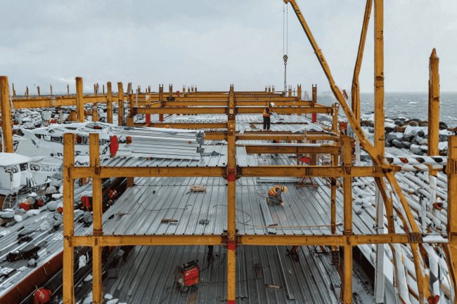
Roof Deck Detailing Checklist Before Fabrication Release
A structured, field-tested walkthrough of every critical checkpoint that structural engineers and detailing coordinators must verify before issuing a roof deck package for fabrication — ensuring accuracy, constructability, and code compliance from the first cut to final delivery.

Why a Pre-Release Checklist Matters
Fabrication release is one of the most consequential milestones in the roof deck detailing process. Before steel enters production, detailers, project managers, engineers, and fabricators still have an opportunity to identify inconsistencies, resolve unanswered questions, and coordinate project requirements at virtually no cost. Once fabrication begins, however, even minor detailing mistakes can escalate into significant schedule impacts, material waste, shop revisions, field modifications, and costly rework.
The Last Zero-Cost Opportunity To Catch Errors
Before fabrication starts, corrections require only review time. After fabrication begins, every correction carries a cost in labor, materials, schedule, and project coordination.
How One Detailing Error Multiplies
What This Checklist Covers
Every fabrication release should be evaluated against six critical detailing categories to ensure the package is complete, coordinated, and ready for production.
Before any deck sheet is sized or detailed, the underlying framing layout must be confirmed as the authoritative basis of the package. Discrepancies between the structural engineer's drawing set and the deck detailer's working files are a leading cause of fabrication rework. Confirm support framing against latest structural issue, verify deck span direction and orientation, and check maximum span against allowable tables are the three critical verification steps that define structural deck readiness.
Verify that all joist, beam, and bearing wall locations used in the deck layout reflect the most current structural drawing revision. Cross-check gridlines, framing member centerlines, and any skewed or non-orthogonal framing conditions.
Confirm that the deck span direction shown on the erection drawing is consistent with the structural design intent. Deck orientation affects load path, diaphragm behavior, and the direction of flute ribs relative to support members.
Confirm that the actual clear span between supports does not exceed the maximum allowable span published in the deck manufacturer's load tables for the specified profile, gauge, and loading condition.
Apply appropriate load combinations per the project's governing code (ASCE 7), including construction live load, superimposed dead load, and any ponding or drift surcharge applicable to the roof zone.
Document minimum bearing lengths at all supports—typically 1.5" minimum at end bearings and 3" at intermediate supports per SDI (Steel Deck Institute) requirements.
Using outdated structural drawings where joist, beam, or bearing wall locations have changed. Results in deck sheets fabricated to wrong dimensions, requiring field modification or complete refabrication.
Inadvertent 90° rotation of deck panels results in spans exceeding allowable limits for selected profile and gauge. May not be visible until deflection or fastener pullout becomes an issue in the field.
Actual clear span between supports exceeds maximum allowable span from manufacturer's load tables. Results in excessive deflection, potential structural failure, and non-compliance with design loads.
Bearing lengths less than SDI minimums (1.5" end, 3" intermediate). Results in inadequate load transfer, potential deck slip, and fastener failure at supports.
Applying incorrect load combinations per ASCE 7. Results in under-designed deck for actual loading conditions, potential over-deflection, and non-compliance with governing code.
Skewed or non-orthogonal framing conditions not properly accounted for in deck layout. Results in custom-cut sheets, increased fabrication complexity, and field fit issues if not detailed correctly.
Request the most current structural drawing revision from the structural engineer. Verify drawing number, revision date, and approval status. Do not proceed with outdated drawings.
Verify all joist, beam, and bearing wall locations against latest structural issue. Cross-check gridlines, framing member centerlines, and any skewed or non-orthogonal framing conditions. Pay particular attention to areas where architectural changes or structural substitutions may have occurred post-design development.
Confirm that the deck span direction shown on the erection drawing is consistent with the structural design intent. Verify deck orientation affects load path, diaphragm behavior, and the direction of flute ribs relative to support members. Check for inadvertent 90° rotation errors.
For each distinct deck zone, confirm that the actual clear span between supports does not exceed the maximum allowable span published in the deck manufacturer's load tables for the specified profile, gauge, and loading condition. Apply appropriate load combinations per ASCE 7.
Document minimum bearing lengths at all supports—typically 1.5" minimum at end bearings and 3" at intermediate supports per SDI requirements. Verify bearing conditions on all structural members.
Before any deck sheet is sized or detailed, the underlying framing layout must be confirmed as the authoritative basis of the package. Obtain sign-off from structural engineer and deck detailer on verified framing layout.
Discrepancies between the structural engineer's drawing set and the deck detailer's working files are a leading cause of fabrication rework. Confirm all three verification steps before proceeding to deck sheet sizing.
Before any deck sheet is sized or detailed, the underlying framing layout must be confirmed as the authoritative basis of the package. Discrepancies between the structural engineer's drawing set and the deck detailer's working files are a leading cause of fabrication rework. Confirm support framing against latest structural issue: verify that all joist, beam, and bearing wall locations used in the deck layout reflect the most current structural drawing revision; cross-check gridlines, framing member centerlines, and any skewed or non-orthogonal framing conditions; pay particular attention to areas where architectural changes or structural substitutions may have occurred post-design development—these are the zones where stale framing data is most likely to surface. Verify deck span direction and orientation: confirm that the deck span direction shown on the erection drawing is consistent with the structural design intent; deck orientation affects load path, diaphragm behavior, and the direction of flute ribs relative to support members; an inadvertent 90° rotation of deck panels can result in spans exceeding the allowable limits for the selected profile and gauge—a critical error that may not be immediately visible in the field until deflection or fastener pullout becomes an issue. Discrepancies discovered after fabrication begin cost exponentially more to fix than discrepancies caught before deck sheets are sized.
Profile and gauge selection must satisfy structural performance requirements, project specifications, and coordination with interfacing systems. These decisions have downstream consequences for every detailing choice in the package.
Common roof deck profiles include 1.5" Type B (standard rib) and 3" Type N (deep rib). Deep-rib profiles provide greater structural depth and insulation cavity but require specific closure and fastener detailing. Always confirm the profile matches the engineer’s specification and is listed in the manufacturer’s load tables.
Confirm base steel gauge (not coating thickness) matches design basis. Typical roof deck gauges range from 22 ga. (lightest) to 16 ga. (heaviest). Thicker gauges are required for longer spans, heavier loads, or enhanced diaphragm capacity. Check each roof zone independently — projects often require multiple gauges.
Deck profile and gauge compliance is not just a specification requirement — it is the foundation of structural performance, diaphragm capacity, and long-term durability. Cross-checking every detail ensures safety and prevents costly rework.
Step 1 — Structural Layout & Span Verification
Confirm Support Framing Against Latest Structural Issue
• All joist locations match latest structural drawing revision
• All beam locations match latest structural drawing revision
• All bearing wall locations match latest structural drawing revision
• Cross-check gridlines (A, B, C... / 1, 2, 3...)
• Cross-check framing member centerlines
• Verify skewed or non-orthogonal framing conditions
• Pay particular attention to areas where architectural changes or structural substitutions may have occurred post-design developmentVerify Deck Span Direction and Orientation
• Load path (direction of force transfer to supports)
• Diaphragm behavior (lateral load distribution)
• Direction of flute ribs relative to support members
• Span direction relative to structural framing
• Deck panel orientation on erection drawing
• Consistency with structural design intentCheck Maximum Span Against Allowable Tables
Span Verification: Critical Parameters
Parameter
Verification Method
Reference Standard
Critical Threshold
Clear Span
Measure actual distance between support centerlines
Structural drawing set (latest revision)
Must not exceed manufacturer's allowable span
Profile & Gauge
Verify deck profile designation and steel gauge
Project specifications, structural notes
Must match load table specifications
Loading Condition
Apply ASCE 7 load combinations
ASCE 7 (project's governing code)
Include construction live load, superimposed dead load, ponding, drift surcharge
Bearing Length
Measure bearing contact at all supports
SDI (Steel Deck Institute) requirements
1.5" minimum at end bearings, 3" at intermediate supports
Span Direction
Verify deck panel orientation on erection drawing
Structural design intent, erection drawings
Must match structural design intent (no 90° rotation errors)
Common Verification Failures and Their Consequences
Verification Workflow: Step-by-Step
Before Any Deck Sheet Is Sized or Detailed, the Underlying Framing Layout Must Be Confirmed as the Authoritative Basis of the Package
The Structural Verification Principle
Profile, Gauge & Spec Compliance
Profile Type Selection
Steel Gauge Verification
Specification Cross-Check Items
Key Insight
Attachment detailing is one of the most critical components of any roof deck fabrication package because it directly determines diaphragm performance, wind uplift resistance, structural load transfer, and code compliance. While deck profile and gauge selection establish the deck's physical capacity, attachment details determine whether that capacity is actually achieved in the finished structure. Every weld, sidelap connection, and perimeter fastener must be clearly defined before release to fabrication.
Roof deck sheets do not create diaphragm strength on their own. Structural performance comes from the attachment system that connects the deck to the supporting structure and joins adjacent panels into one continuous load-resisting assembly.
Unspecified sidelap attachment creates uncertainty in diaphragm performance and may invalidate the assumptions used in the structural design calculations.
Enhanced perimeter attachment requirements should be explicitly shown on erection plans rather than buried within general notes.
Attachment schedules must match the exact weld patterns, sidelap spacing, and perimeter fastening assumptions used within the diaphragm design calculations. Design capacity and detailing capacity must remain aligned.
Fastener patterns should never be viewed as secondary information. They define diaphragm strength, uplift resistance, load transfer mechanisms, and code compliance. Complete attachment detailing is one of the most important quality-control checks performed before fabrication release.
Successful roof deck fabrication packages fully define puddle weld patterns, sidelap fastening schedules, perimeter attachment requirements, weld specifications, and diaphragm-related connection details before release. Thorough attachment detailing eliminates ambiguity, protects structural performance, reduces field questions, and ensures the fabricated package accurately reflects the engineer's intended diaphragm design.
Step 3 — Attachment, Fastener & Sidelap Detailing
The Diaphragm Is Only As Strong As Its Connections
Three Critical Attachment Categories
Never Leave Sidelap Fastening To Field Judgment
Attachment Density by Roof Zone
Cross-Reference Every Fastener Schedule
Substitution Control
Attachment Details Are Structural Details
Document Every Connection Before Steel Reaches The Shop
The final three checkpoint categories address the coordination-intensive details that most frequently generate RFIs, field conflicts, and schedule holds. These items require active coordination with the structural engineer, mechanical/electrical trades, and the fabricator before the package is released. Closures, pour stops & accessories, opening coordination & framing details, and drawing & document completeness are the three critical verification steps that define fabrication package readiness.
All open ribs at deck ends, edges, and penetrations must be closed to prevent concrete migration (on composite systems) and to provide a finished bearing condition. Confirm that closure types are detailed for every condition.
Every opening through the roof deck—whether for mechanical curbs, skylights, hatches, pipe penetrations, or structural frames—must be located, sized, and framed before fabrication release.
The package should include: a fully dimensioned erection plan with gridlines and panel layout; a fastener/weld schedule for all zones; a deck schedule cross-referencing profile, gauge, coating, and zone designation; all required section and detail views for non-standard conditions; and references to the governing project specification sections.
Confirm that the fabricator has received the latest structural drawing revision and that any RFIs affecting deck scope have been formally resolved. A pre-release coordination call with the fabricator is strongly recommended for complex or large-scale roof systems.
Before issuing the fabrication package, verify that all documents are current-revision, internally consistent, and complete. All documents must be current-revision (latest structural drawing revision), internally consistent (no conflicts between drawings), and complete (no missing details or schedules).
Open ribs at deck ends, edges, or penetrations not closed. Results in concrete migration (on composite systems), unfinished bearing conditions, and field-installed closures that delay schedule and increase cost.
Openings not coordinated with MEP drawings. Results in field-cut openings that conflict with structural framing, require supplemental framing not shown on drawings, and generate RFIs that halt installation.
Headers, trimmers, or ledger angles not shown on structural drawings or reflected in deck erection plan. Results in field-fabricated framing, structural engineer RFIs, and potential diaphragm capacity reduction.
Fabricator working from outdated structural drawing revision. Results in fabricated deck sheets that don't match current framing layout, requiring refabrication or field modification at significant cost and schedule impact.
RFIs affecting deck scope not formally resolved before fabrication release. Results in fabricated deck that may not meet structural intent, requiring change orders, rework, or acceptance of non-conforming conditions.
Section and detail views for non-standard conditions not included in package. Results in field interpretation errors, inconsistent installation, and potential structural or waterproofing failures at complex conditions.
All open ribs at deck ends, edges, and penetrations closed in details. Closure types (standard rib closures, custom bent plate, or formed closures) detailed for every condition including valleys, ridges, hip and valley conditions on sloped roofs, and eave conditions. Pour stops sized for wet concrete head pressure where applicable. Specialty accessories (vented ridge closures, acoustical infill, foam closure strips) itemized and coordinated with fabricator's standard product offerings.
Every opening through the roof deck located, sized, and framed before fabrication release. Opening dimensions coordinated with MEP drawings. All required supplemental framing (headers, trimmers, ledger angles) shown on structural drawings and reflected in deck erection plan. Openings larger than single flute width explicitly noted for field cutting. Openings in diaphragm-critical zones reviewed by engineering for shear transfer impact assessment.
All documents current-revision, internally consistent, and complete. Package includes: fully dimensioned erection plan with gridlines and panel layout; fastener/weld schedule for all zones; deck schedule cross-referencing profile, gauge, coating, and zone designation; all required section and detail views for non-standard conditions; references to governing project specification sections. Fabricator has received latest structural drawing revision. Any RFIs affecting deck scope formally resolved. Pre-release coordination call with fabricator completed for complex or large-scale roof systems.
The final three checkpoint categories address the coordination-intensive details that most frequently generate RFIs, field conflicts, and schedule holds. Complete all three steps before releasing fabrication package.
The final three checkpoint categories address the coordination-intensive details that most frequently generate RFIs, field conflicts, and schedule holds. These items require active coordination with the structural engineer, mechanical/electrical trades, and the fabricator before the package is released. Closures, pour stops & accessories: all open ribs at deck ends, edges, and penetrations must be closed to prevent concrete migration (on composite systems) and to provide a finished bearing condition; confirm that closure types (standard rib closures, custom bent plate, or formed closures) are detailed for every condition—including valleys, ridges, hip and valley conditions on sloped roofs, and eave conditions; pour stops must be sized for wet concrete head pressure where applicable; specialty accessories such as vented ridge closures, acoustical infill, and foam closure strips must be itemized and coordinated with the fabricator's standard product offerings. Opening coordination & framing details: every opening through the roof deck—whether for mechanical curbs, skylights, hatches, pipe penetrations, or structural frames—must be located, sized, and framed before fabrication release; confirm that opening dimensions are coordinated with the mechanical/electrical/plumbing (MEP) drawings and that all required supplemental framing (headers, trimmers, ledger angles) is shown on the structural drawings and reflected in the deck erection plan; openings larger than a single flute width typically require field cutting—but this must be explicitly noted; openings in diaphragm-critical zones require engineering review to assess the impact on shear transfer. Coordination failures discovered after fabrication release cost exponentially more to fix than coordination failures caught before package release.
Steps 4–6 — Closures, Openings & Document Completeness
Closures, Pour Stops & Accessories
• All open ribs at deck ends must be closed
• All open ribs at deck edges must be closed
• All open ribs at penetrations must be closed
• Prevent concrete migration (on composite systems)
• Provide finished bearing condition
• Confirm closure types detailed for every condition
• Standard rib closures
• Custom bent plate
• Formed closures
• Valleys (roof valleys)
• Ridges (roof ridges)
• Hip and valley conditions on sloped roofs
• Eave conditionsOpening Coordination & Framing Details
• Mechanical curbs (HVAC equipment)
• Skylights (roof glazing)
• Hatches (roof access)
• Pipe penetrations (plumbing, mechanical)
• Structural frames (columns, beams through deck)
• All other roof penetrations
• Confirm opening dimensions are coordinated with MEP drawings
• All required supplemental framing shown on structural drawings
• Supplemental framing reflected in deck erection plan
• Headers, trimmers, ledger angles detailed
• Openings larger than single flute width explicitly noted for field cutting
• Openings in diaphragm-critical zones require engineering reviewDrawing & Document Completeness: Before Issuing the Fabrication Package, Verify That All Documents Are Current-Revision, Internally Consistent, and Complete
Document Completeness Checklist
Document Type
Required Content
Verification Check
Status
Erection Plan
Fully dimensioned with gridlines and panel layout
All dimensions present, gridlines match structural, panel layout complete
✓ Required
Fastener/Weld Schedule
Schedule for all zones (deck-to-structure, sidelaps, endlaps)
All zones covered, fastener types specified, spacing defined
✓ Required
Deck Schedule
Cross-referencing profile, gauge, coating, and zone designation
All zones listed, profile/gauge/coating specified, matches structural
✓ Required
Section & Detail Views
All required sections and details for non-standard conditions
All non-standard conditions detailed, sections dimensioned
✓ Required
Specification References
References to governing project specification sections
All spec sections referenced, current revision, no conflicts
✓ Required
Closure Details
All closure types detailed for every condition
Ends, edges, penetrations, valleys, ridges, hips, eaves all detailed
✓ Required
Opening Details
All openings located, sized, and framed with supplemental framing
All openings coordinated with MEP, framing shown, field cutting noted
✓ Required
Latest Structural Revision
Fabricator has received latest structural drawing revision
Revision number confirmed, date verified, fabricator acknowledged
✓ Required
RFI Resolution
Any RFIs affecting deck scope formally resolved
All RFIs closed, responses documented, no open deck-scope RFIs
✓ Required
Common Coordination Failures and Their Consequences
Pre-Release Coordination Checklist
Before Issuing the Fabrication Package, Verify That All Documents Are Current-Revision, Internally Consistent, and Complete
The Package Completeness Principle
What's Your Reaction?