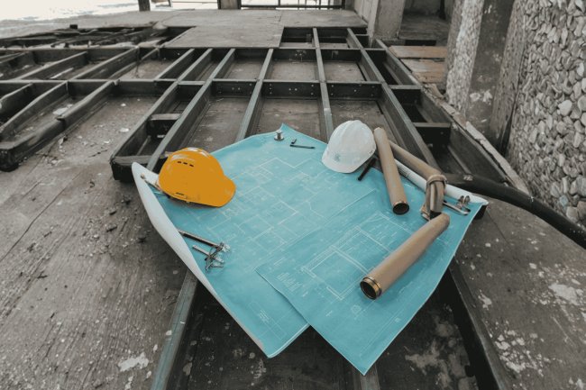
Roof Deck Detailing Near Parapet Lines
The interface between a structural roof deck and a parapet wall is one of the most technically demanding zones in steel-framed building design. It concentrates thermal movement, lateral load transfer, waterproofing transitions, and code-driven anchorage requirements into a narrow strip of structure — one that is often under-detailed in early design phases and consequently corrected in the field at significant cost. This presentation walks through the critical principles, common failure modes, and best-practice detailing strategies that structural engineers and detailers must understand to produce accurate, constructible, and code-compliant roof deck assemblies at parapet lines.
Why the Parapet Zone Demands Special Attention
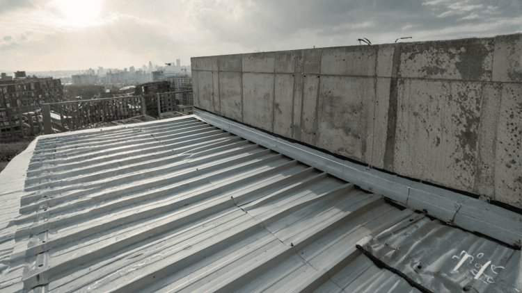
Most roof deck areas follow repetitive framing patterns and well-established manufacturer design guidance. The parapet zone is fundamentally different. It represents the convergence of structural framing, diaphragm behavior, roofing assemblies, thermal control layers, and enclosure systems. Because these systems interact directly at the roof perimeter, small detailing mistakes can lead to water intrusion, structural discontinuities, thermal bridging, and costly field modifications.
The Parapet Is a Multi-System Interface
Envelope & Waterproofing Interface
Roofing membranes terminate at or near the parapet cap. Successful waterproofing therefore depends upon maintaining a stable, continuous, and properly supported substrate beneath the membrane system.
Thermal Bridging Risk
Steel deck and support connections readily transfer heat. At parapet transitions, uninsulated connections can create thermal bridges that contribute to condensation, corrosion, reduced energy efficiency, and long-term deterioration of roof edge components.
Diaphragm Continuity
Perimeter chord members, edge connections, weld patterns, and deck attachment schedules establish the diaphragm boundary. Weak or incomplete connections can interrupt load transfer where diaphragm forces are frequently at their highest.
A reliable parapet line is a coordinated assembly of bearing, edge restraint, closure, flashing support, and diaphragm attachment. Each element must be designed for the actual geometry and load path.
A continuous angle, such as an L4×3½×⅜ where appropriate, can provide deck bearing and a load-transfer interface at the parapet. The selected size is project-specific and must be checked for bearing, shear, tension, deflection, corrosion, and connection capacity.
Open flutes can permit air, moisture, vermin, smoke, and fire migration within the deck system. Select a profile-compatible closure and define whether it is structural, environmental, or both.
Perimeter attachments usually require more attention than field attachments because the edge transfers diaphragm forces and may experience higher uplift.
Size the welds, bolts, plates, anchors, and supporting substrate for the combined demand.
Show bearing, end attachment, rib closure, and any special perimeter pattern.
Coordinate closure projection, flashing, insulation, membrane, and fire-separation requirements.
Document chord and shear transfer rather than assuming typical field attachments apply.
Use the approved typical pattern for ordinary demand, subject to the governing design table.
Use the engineer’s edge schedule for uplift, chord, and diaphragm transfer. Do not assume a universal 6-in. pattern.
Check closer or specialized patterns where the approved diaphragm design requires them; published examples are not substitutions for project calculations.
A closure that seals a flute may not resist load or transfer diaphragm force.
A parapet detail succeeds when the ledger angle bears the deck, the closure controls the rib, the attachment schedule transfers the diaphragm demand, and the roofing system receives a continuous, coordinated substrate. Design the interface as one assembly—not three separate trades.
Key Detailing Elements at the Roof Deck–Parapet Interface
Perimeter Structural Support
Edge Closure and Flute Blocking
Welds and Fastener Zones
Detail Each Interface Explicitly
Attachment Pattern Discipline
A Closure Is Not Automatically Structural
Parapet Release Checklist
The Parapet Principle
Steel roof decks expand and contract with temperature swings. A 200-foot deck can move over 1½ inches across a 120°F range. If parapet details ignore this predictable movement, the result is cracked masonry, torn flashings, or buckled panels.
The formula for thermal movement is: Never assume parapet walls act as fixed anchors. Masonry and concrete parapets move independently, creating differential demands at every connection.
The deck-parapet intersection collects water from rain, condensation, and drainage. Specify galvanized or painted ledger angles, stainless fasteners in humid/coastal zones, and slope the deck (¼" per foot) away from the parapet toe toward drains.
Thermal movement is predictable and must be engineered into parapet details. Expansion joints, slotted anchors, flexible sealants, and corrosion-resistant materials prevent progressive failures and extend roof system life.
Thermal Movement: The Overlooked Driver of Parapet Failures
Movement Accommodation Strategies
Calculating Thermal Demand
ΔL = α × L × ΔT, where α = 6.5 × 10⁻⁶ in/in/°F. Example: For a 150-ft run with ΔT = 100°F, ΔL = 1.17 inches — enough to shear welds or crack parapets if not accommodated.
Corrosion at the Parapet Toe
Key Insight
The parapet boundary defines the edge of the roof diaphragm and often represents the most structurally demanding portion of the roof deck system. At this location, diaphragm shear, chord forces, collector action, wind uplift, roofing interfaces, and construction tolerances converge within a highly congested zone. Successful diaphragm detailing depends on creating a clear, continuous, and fully documented load path from the roof deck field into the building's lateral-force-resisting system.
At braced frames and shear walls, diaphragm forces must be transferred through a complete load path into the building's lateral-force-resisting system. This transfer cannot be assumed; every component participating in the load path should be explicitly detailed.
When deck panels run parallel to the parapet, diaphragm force transfer depends heavily on sidelap connections, edge fastening patterns, and perimeter support geometry. These conditions frequently require heavier fastening schedules than perpendicular layouts.
Successful diaphragm design at the parapet boundary depends on explicit detailing of every force-transfer component. Chords, collectors, deck attachments, splices, and lateral-force-resisting elements should be connected by a documented load path that remains continuous through every discontinuity, opening, and geometric irregularity.
While diaphragm capacity is often associated with deck profiles and fastening schedules, true performance is governed by the perimeter where forces leave the diaphragm and enter the building structure. Comprehensive parapet detailing ensures that lateral loads travel through a clear, continuous, and constructible load path from roof deck to LFRS without interruption.
Diaphragm Design Coordination at the Parapet Boundary
The Parapet Boundary Is a Force Transfer Zone
Shear Transfer into the LFRS
Parallel Deck Layouts Require Additional Scrutiny
High-Risk Discontinuities Requiring Explicit Detailing
Diaphragm Coordination Workflow
The Load Path Must Be Drawn, Not Assumed
The Strongest Diaphragm Is Only as Strong as Its Boundary
Resolve parapet-zone conflicts during structural drawing review, before shop drawing approval and construction. The strongest review is interdisciplinary: structural, roofing, envelope, and coordination leads evaluate one complete load path.
Include at least one large-scale detail for each typical parapet condition, with the deck, ledger angle, closure, fasteners, parapet, flashing, insulation, and membrane termination labeled by function.
Showing deck terminating at masonry or a parapet without a structural bearing element leaves the contractor guessing and prevents meaningful inspection.
Coordinate deck elevation with parapet height, insulation thickness, finished roof level, coping, flashing termination, and membrane requirements before shop drawings are submitted.
Expansion joint location, panel length, sliding clips, cover plates, flashing, and parapet transitions must be designed—not delegated to a contractor’s generic solution.
Ledger angles, closures, clips, fasteners, anchors, and weld interfaces need a project-specific corrosion-protection basis tied to exposure, material compatibility, and the envelope design.
A general interior/edge/corner note is not enough on an irregular perimeter. The installer must be able to identify exactly where each pattern starts, stops, and changes.
Deck bears at masonry or parapet without a defined structural support element.
The perimeter chord is interrupted at a column without a force-designed splice.
Rigid deck-to-masonry connections accumulate movement without joints or sliding provisions.
Deck, insulation, flashing, coping, and membrane elevations do not align.
If not, return to the design review.
Resolve parapet detailing while the design is still easy to change. A complete load-path detail, coordinated elevation, engineered movement, explicit corrosion protection, and plan-level fastening schedule will prevent more problems than a late shop-drawing correction ever can.
Best Practices, Common Errors & Detailing Checklist
Best Practice: Detail Every Condition
Common Error: Missing Ledger Angle
Best Practice: Lock Elevations Early
Best Practice: Engineer Movement
Specify Corrosion Protection
Common Error: Perimeter Pattern Ambiguity
Critical Error Checks
Interdisciplinary Review Gate
Can the Field Build It Without Guessing?
The Peer-Review Principle
What's Your Reaction?