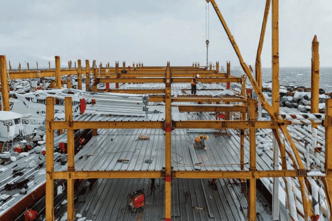
How Deck Rib Orientation Affects Support Layout
The direction metal deck ribs run across a structural bay is far more than an aesthetic or detailing afterthought — it is a fundamental design decision that cascades directly into beam spacing, joist layout, connection strategy, and overall structural efficiency. Whether ribs span perpendicular or parallel to the primary framing members, each orientation carries distinct structural implications that must be resolved early in the design process to avoid costly coordination conflicts downstream. This guide examines the mechanical logic behind rib orientation, the practical rules that govern support spacing for each case, and the detailing consequences that structural and connection engineers must anticipate and resolve.

Understanding Metal Deck Rib Orientation
Before spans, gauges, or support layouts are evaluated, engineers must first understand how the deck ribs are oriented relative to the framing. This single decision fundamentally changes structural behavior.
How Load Paths Change
Rib direction determines how the deck spans, which span table applies, and how supporting members must be spaced. These are structural requirements—not drafting preferences.
End spans are typically treated as single, simply supported spans. They do not receive the same continuity benefit as interior spans, especially where the deck terminates at the building perimeter.
Deck continuous over three or more supports can achieve lower midspan moment and deflection. Detailers must verify that the actual support layout matches the continuity assumed by the selected span table.
Coordinate rib direction with the structural framing plan before shop drawings begin. A change in orientation can alter allowable span, support spacing, composite behavior, diaphragm performance, drainage, and the need for supplemental bracing.
Support Spacing Rules Driven by Rib Orientation
End Spans
Interior Continuous Spans
Rib orientation is not chosen in isolation — it is the downstream consequence of how primary beams and secondary joists are arranged. The framing layout and deck orientation form a feedback loop that engineers must resolve deliberately.
Open-web steel joists are the most common supports. Their spacing is bounded by deck span capacity:
Cross-reference joist load tables with deck span tables. Ribs perpendicular to joists = efficient; parallel ribs require reduced spacing and supplemental framing.
Bay aspect ratio drives rib orientation:
Guiding principle: orient ribs across the shorter bay dimension to maximize supports. Bay widths >16–20 ft with light gauges require intermediate joists regardless.
The framing plan must explicitly call out rib orientation with arrows or notes. Mismatches between plan notation and field installation are a common source of RFIs.
Best practice: include a dedicated deck orientation plan showing orientation zones, transitions, and parallel-to-support conditions. This becomes the primary reference for installers and inspectors.
Joist spacing, beam orientation, and explicit coordination in drawings are inseparable. Treating deck orientation as an afterthought leads to inefficiency and non-conformance. Resolve orientation deliberately at the design stage.
Joist and Beam Layout Implications
Joist Spacing Dictated by Deck Span
Primary Beam Orientation & Bay Ratio
Coordination with the Framing Plan
Key Takeaway
Real structures rarely maintain a single deck orientation throughout the entire floor plate. Changes in rib direction create concentrated detailing demands that require dedicated structural support, fastening requirements, and explicit coordination between design and construction teams.
Detailing Consequences at Orientation Transitions
Where Detailing Complexity Occurs
Parallel Deck Condition
Orientation Change
Interrupted Ribs
Fastening Becomes More Important During Transitions
Rib orientation is a structural decision—not a field call. Locking it in early prevents reframing, unplanned joists, MEP conflicts, and diaphragm deficiencies.
Check the deck span table and joist load table at the same time. The governing spacing is the more restrictive result, including construction-stage loading where the deck is unshored.
Record the controlling table reference for each bay to simplify peer review and future RFI resolution.
Mark every parallel-to-support zone with a distinct boundary or callout. Reference a dedicated detail showing rib closures, edge fastening, reduced support spacing, and supplemental framing.
For complex geometry, multiple profiles, or high diaphragm demand, issue a dedicated plan that becomes the shared reference for the installer, inspector, detailer, and peer reviewer.
When orientation is treated as an afterthought, the consequences appear as added framing, diaphragm deficiencies, pour-stop failures, and repeated submittal cycles. Put the decision on the drawings early, coordinate it across disciplines, and detail every exception explicitly.
Getting Rib Orientation Right from the Start
Size Deck and Joists Together
Flag and Detail Explicitly
Create an Orientation and Fastening Plan
The Drawing-Set Principle
What's Your Reaction?