Precast Concrete Quality Control: A Fabrication and Erection Inspection Checklist
Quality control in precast concrete is not a single checkpoint — it is a continuous discipline woven through every phase of production, from the moment a shop drawing is reviewed to the final bolt tightened on a completed structure. For fabricators, engineers, and site inspectors, a rigorous QA/QC framework is the difference between structures that perform as designed and costly rework, structural failures, or project delays.

Pre-Fabrication: Drawings, Mix Design, and Reinforcement Verification
The foundation of effective precast quality control is established long before concrete is poured. Pre-fabrication review ensures that every element — from approved shop drawings to material certifications — meets specification requirements before production begins.
Approved Shop Drawing Review
No fabrication should commence without engineer-of-record approved shop drawings. Inspectors must verify that drawings reflect the latest revision, carry all required approval stamps, and accurately depict element geometry, reinforcement layout, embed plate locations, lifting insert positions, and connection hardware details.
Any discrepancy between the contract drawings and shop drawings must trigger a formal RFI before work proceeds.
Cross-check that tolerance requirements align with PCI MNL-116 (Manual for Quality Control for Plants and Production of Structural Precast Concrete Products) and applicable project specifications. Confirm that mix design submittals, aggregate gradations, admixture data sheets, and cement mill certificates have been reviewed and approved by the engineer of record.
Reinforcement, Embedments & Lifting Inserts
Steel placement is among the most critical pre-pour inspection items. Verify bar sizes, grades (ASTM A615 / A706), spacing, and cover dimensions against approved drawings. Check that splices, lap lengths, and hooks conform to ACI 318 requirements. Stirrup and tie spacing must be measured at multiple points — not just at the ends of elements.
Embedding plates, anchor bolts, bearing pads, and mechanical connections must be precisely positioned and securely fastened to prevent displacement during vibration.
Lifting inserts — coil inserts, Meadow Burke or equivalent — must be verified for load rating, embedment depth, and orientation. Inspect strand profiles for prestressed elements, confirming hold-down and hold-up points as drawn. Document all pre-pour inspections with signed inspection reports before concrete placement is authorized.
Submittal & Drawing Approval
Obtain engineer-approved shop drawings, mix designs, and material certs before any work order is released to the production floor.
Form & Bed Setup Inspection
Inspect formwork geometry, side form alignment, and bulkhead positions against drawing dimensions. Check form release agent application and cleanliness.
Reinforcement Pre-Pour Inspection
Conduct a formal walk-through of all steel placement, embed positions, lifting hardware, and strand layout. Sign the pre-pour inspection record.
Concrete Placement Authorization
Issue written authorization to place concrete only after all pre-pour items are verified, documented, and signed off by the designated inspector.
Most precast quality issues originate before concrete placement. Thorough verification of drawings, materials, reinforcement, embedments, prestressing systems, and lifting hardware is the strongest defense against fabrication defects, field failures, and costly corrective work.
Effective precast quality control begins long before the pour. When drawings, materials, reinforcement, embedments, and inspection procedures are verified correctly, production quality becomes predictable, repeatable, and compliant.
Post-stripping inspections are where fabrication quality is validated against dimensional tolerances and surface finish standards. Inspectors must work from a printed copy of the approved shop drawing and systematically record measurements at defined checkpoints for every unique element type.
Measure overall length, width, and depth at multiple points. PCI MNL-116 tolerances for overall length typically allow ±¼" for elements under 20 ft, ±⅜" for 20–40 ft, and ±½" beyond 40 ft. Record actual versus specified at each measurement location.
Check diagonal measurements to confirm squareness. Measure sweep (bow in plan) and camber (bow in elevation) using a taut wire or laser level. Compare against PCI tolerance tables for the specific element classification.
After stripping, verify that embed plates, anchor bolts, sleeves, and lifting inserts are positioned within drawing tolerances — typically ±¼" in plan and elevation. Measure and record deviations for the project file.
Use a cover meter or break-out test to confirm reinforcing steel cover meets specification minimums. Inadequate cover is a critical non-conformance requiring engineering review before acceptance.
Surface quality must be evaluated against the specified finish class for each element face. The PCI finish classification system defines standards from As-Cast (AC) through Grout-Cleaned (GC) and Smooth Rubbed (SR) finishes for architectural elements. Inspect for the following defects and document severity:
Honeycombing — exposed aggregate areas with insufficient mortar; classify depth and area
Bug holes — surface voids from air entrainment against form face; allowable limits vary by finish class
Cold joints — visible layer lines indicating interrupted placement; typically a structural concern
Form-face staining — oil streaks or rust marks requiring remediation on architectural elements
Cracking — hairline vs. structural; document location, length, width, and orientation for engineering evaluation
Spalls and chips — from stripping or handling; assess whether within allowable limits or requiring patching
All patching work must follow an approved repair procedure and be performed by qualified personnel. Repaired areas should be documented with before/after photos in the element's inspection record.
Learn more about structural concrete systems at Consac.com.
Cylinder breaks are the primary evidence of concrete strength adequacy. For prestressed elements, minimum compressive strength at detensioning (transfer strength) is a critical hold point — typically 3,500 to 4,000 psi minimum, as specified. Release of prestress before achieving transfer strength is a major non-conformance.
Inspect curing records to confirm that steam or wet-curing procedures were followed per the approved curing plan. Temperature logs for steam-cured elements must document maximum temperature ramp rates (typically not exceeding 40°F/hr) and maximum curing temperature (usually ≤160°F) to prevent delayed ettringite formation (DEF). Confirm that 28-day design strength cylinders are properly stored, identified, and submitted to an accredited testing laboratory.
Verify transfer strength before detensioning — this is a mandatory hold point
Review steam curing temperature logs for every pour
Confirm cylinder identification matches batch tickets
Document 7-day and 28-day break results in the QC log
Failure to achieve transfer strength before strand release is among the most common and consequential QC failures in prestressed fabrication. Establish this as a formal hold point in your QCP.
Dimensional Inspections & Concrete Surface Quality
Overall Dimensions
Squareness & Sweep
Embed & Insert Locations
Concrete Cover
Surface Finish Classifications
Concrete Strength & Curing Verification
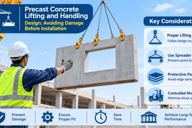
Quality control does not end at the plant gate. Transportation stresses, improper blocking, rough handling, and poor erection practices can compromise elements that left the plant in perfect condition. A structured site inspection protocol protects both the structure and the project schedule.
Document transportation condition, erection tolerances, connections, grouting, and final structural checks at every hold point.
Transportation, Site Erection
& Final InspectionProtect the structure and the schedule—from plant gate to final inspection.
A quality control program is only as strong as its documentation. Inspection records, testing reports, quality logs, and non-conformance documentation provide the verifiable evidence required to demonstrate compliance with contract specifications, building codes, PCI plant certification standards, and regulatory requirements. Without complete records, even exemplary inspection practices become difficult to defend after project completion.
Every PCI-certified precast facility must maintain a documented Quality Control Plan outlining inspection procedures, testing frequencies, hold points, accepted tolerances, corrective-action procedures, inspector responsibilities, and record-retention requirements.
Project-specific requirements exceeding standard PCI criteria should be incorporated into the QCP before production begins and distributed to all relevant personnel.
Every precast element should maintain a complete traceable record connecting shop drawing revisions, concrete batch data, strength-test results, pre-pour inspections, dimensional surveys, repair history, and final acceptance documentation.
Element mark numbers serve as the primary identification method and create continuity throughout fabrication, shipping, erection, and project closeout processes.
Every specification deviation should trigger a formal NCR process. Documentation must include objective evidence, dimensional data, photographs, affected piece numbers, root-cause information, and recommended corrective actions.
Dispositions such as Use-As-Is, Repair, Reject-and-Replace, or Return-for-Rework require engineering review and approval before affected components enter the structure.
Ongoing inspections performed by qualified plant personnel throughout fabrication and finishing operations.
Independent testing agencies verify material properties, concrete strength, and conformance to project requirements.
Jurisdiction-required inspections performed under approved programs with reporting submitted to the Authority Having Jurisdiction.
Exceptional quality systems extend responsibility beyond the QC department. Form setters, reinforcing crews, finishers, yard personnel, truck drivers, and field erection teams all contribute directly to quality outcomes. Regular training, documented competency records, toolbox talks, process audits, and rapid corrective-action implementation reinforce the expectation that quality ownership belongs to everyone involved in production and installation.
PCI certification programs provide an independent framework for measuring, maintaining, and continuously improving fabrication quality systems while providing confidence to owners, engineers, and contractors.
Every precast element should be linked to drawings, batches, inspections, testing, and repairs.
Typical minimum record-retention duration for structural precast documentation.
All specification deviations should trigger documented corrective-action review.
Documentation is more than a contractual requirement—it is the foundation of accountability, risk management, and continuous improvement. By tracking NCR trends, analyzing recurring defect categories, reviewing inspection data, and implementing corrective actions based on objective evidence, precast producers continuously strengthen manufacturing performance. Consistent documentation protects against disputes, supports regulatory compliance, and provides the strongest evidence of professional diligence throughout the life of a project.
Documentation, Inspection Records & Non-Conformance Management
Quality Control Plan (QCP)
Inspection Records & Batch Documentation
Non-Conformance Reports (NCRs)
Inspection & Compliance Framework
Internal QC Inspections
Third-Party Testing
Special Inspections
Key Documents in a Precast QC File
Building a Culture of Quality
Continuous Improvement Through Documentation
What's Your Reaction?