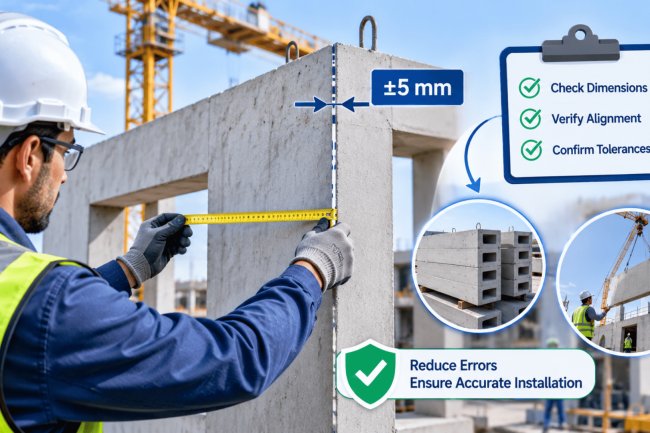
Precast Concrete Transportation Planning: How Detailing Impacts Logistics and Delivery
In the precast concrete industry, successful delivery is not an afterthought — it is an outcome of decisions made weeks or even months before the first truck rolls out of the plant. Transportation planning begins at the drafting table. The dimensions you specify, the embedments you place, and the weight distribution you calculate during detailing directly determine whether your panels arrive on-site intact, on schedule, and in the correct sequence for erection.

Why Transportation Planning Begins During Detailing
The Detailing–Logistics Connection
Every dimension, embed location, and connection detail recorded during the detailing phase has a downstream effect on how a panel can be safely transported. Panel length determines whether a standard 48-foot flatbed is sufficient or whether a permit oversize load is required. Panel thickness and reinforcement layout affect weight-per-linear- foot calculations. Lifting insert placement governs how a panel can be rigged, tilted, and secured during transit.
Detailers who treat transportation as a separate discipline — something for the yard crew to figure out after fabrication — introduce costly rework, cracked panels, and missed delivery windows. The most efficient precast operations integrate logistics constraints into the shop drawing review process from day one.
Panel Dimensions, Weight & Center-of-Gravity Calculations
Before any panel leaves the drawing board, engineers must confirm three critical values: overall dimensions, shipping weight, and center of gravity (CG). Oversize panels — those exceeding 8'6" in width, 13'6" in height when vertical, or 80,000 lbs gross vehicle weight — require state transportation permits, escort vehicles, and route surveys that add days or weeks to project schedules.
Center-of-gravity calculations are especially critical for non-rectangular panels such as spandrels, corbeled columns, or L-shaped sections. An off-center CG creates uneven load distribution on the trailer, increases the risk of tipping, and can cause bending stresses in transit that exceed what the panel was designed to handle. Detailing engineers should document CG coordinates on shop drawings and communicate them directly to the yard and shipping coordinator.
Essential Pre-Shipment Verification
Dimensional Compliance
Verify panel length, width, and height against state DOT oversize load thresholds early in design. Changes after fabrication are expensive and often impossible.
Weight Calculations
Calculate shipping weight including all embedded hardware, blockouts, and any cast-in temporary supports. Normal weight concrete runs approximately 150 pcf — lightweight mixes change the equation significantly.
CG Documentation
Document center-of-gravity coordinates on every non-standard panel. Share with the rigging crew and truck driver so dunnage and tie-down points can be set correctly in the yard.
Transportation success is determined long before a panel reaches the trailer. Dimensions, weight, center of gravity, lifting hardware, and route constraints should all be validated during detailing to avoid fabrication changes, shipping delays, damaged panels, and costly field disruptions.
The most successful precast projects treat transportation as a design constraint from day one, integrating logistics, rigging, weight distribution, and dimensional limits directly into the detailing process.
Precast panels are not designed to be simply laid flat on a trailer deck. Many wall panels, double-tees, and spandrels must be transported in a specific orientation — typically upright or slightly inclined — to prevent bending stresses that exceed their in-transit structural capacity.
Temporary transportation supports, A-frames, and shipping racks must be specified during the detailing phase, not improvised in the yard. Detailers should identify all panels that require upright shipping early in the shop drawing process and communicate A-frame or cradle requirements to the yard superintendent. Temporary connection hardware — including shipping angles, web stiffeners for double-tees, and corner protection brackets — should be called out on drawings with material specifications and removal instructions for the erection crew.
Specify A-frame or shipping rack type on panel erection drawings
Detail temporary weld plates or bolted connections for panels shipped upright
Include dunnage location, material, and bearing area on shipping plans
Note maximum stacking height for horizontal panels to prevent overstress
Truck loading is both a structural and logistical exercise. The goal is to maximize payload per trip while keeping the load within legal weight limits per axle, maintaining trailer stability, and ensuring panels can be offloaded at the site in erection sequence. Delivery sequencing — ensuring that panels arrive in the order they are needed for installation — is one of the most underappreciated aspects of precast logistics coordination.
A poorly sequenced delivery forces the erection crew to shuffle panels around the site using costly crane time, damages panel edges and finishes, and delays the critical path. Work with the general contractor's site superintendent to map the erection sequence before finalizing the production and shipping schedule. Panels needed first should be fabricated and shipped last so they sit on top of the load or arrive on the final truck of the day.
Map erection sequence to truck load order — last-in, first-out principle applies
Confirm site crane capacity and reach before loading oversized panels
Communicate delivery windows to the GC at least 48–72 hours in advance
Use panel ID tags visible from the cab for quick field identification
Timed Delivery
Secure Plan
Load Panels
Confirm Order
Transportation Restraints, Temporary Supports & Truck Loading Configurations
Designing for Restraint: Temporary Supports in Transit
Truck Loading Configurations & Delivery Sequencing
Cracked or chipped precast panels discovered at the job site create a cascade of problems: project delays while replacement panels are fabricated, disputes over responsibility between the plant and the GC, costly patching that may not match the original finish, and—in structural elements—potential rejection by the engineer of record. Most transit damage is preventable when detailing, yard operations, and shipping are coordinated properly.
Proper dunnage, edge protection, wrapping, speed limits, and verified tie-down ratings prevent most transit damage—and the delays, disputes, and remediation costs that follow it.
Preventing Cracking & Damage
During TransportationCoordinate detailing, yard operations, and shipping before departure.
The most successful precast projects are not defined solely by engineering quality or manufacturing efficiency. They succeed because plant production schedules and field installation requirements operate as a single coordinated system. Bridging the gap between fixed manufacturing cycles and dynamic construction-site realities requires disciplined communication, proactive planning, and continuous schedule alignment from project kickoff through final erection.
Align fabrication sequencing with the planned erection sequence during shop drawing review. Identify special finishes, long-lead embeds, custom connection hardware, and specialty materials that may influence production timing.
Establish milestone dates for panel groups, track manufacturing progress continuously, and provide regular production updates so erection teams can coordinate labor, crane scheduling, and site logistics effectively.
Issue delivery notifications well in advance and verify that cranes, unloading zones, access routes, staging areas, and temporary supports are fully prepared before shipment leaves the plant.
Capture panel fit-up issues, handling damage, sequence challenges, and erection observations in real time and communicate them directly back to manufacturing teams to improve subsequent deliveries.
When project schedules shift later, finished precast components consume valuable storage space, occupy yard capacity, and require ongoing protection from weather and physical damage. Establish storage limitations and associated fee structures early so all parties understand the cost impact of schedule delays.
Accelerated construction activities require flexible manufacturing capacity. Maintaining production buffers between planned strip dates and shipment dates provides the adaptability needed to support critical-path erection demands.
Bring together the GC, erector, precast producer, transportation provider, and project management team before production begins.
Monitor every panel through fabrication, curing, finishing, storage, and shipment using a shared project dashboard.
Establish one dedicated logistics coordinator responsible for all delivery communication and schedule updates.
Maintain contingency allowances for weather interruptions, procurement delays, production disruptions, and crane availability conflicts.
Successful precast logistics depends on treating fabrication, transportation, and installation as a single integrated workflow rather than independent activities. The strongest projects maintain continuous communication, transparent production visibility, and proactive schedule management from shop drawing approval through final erection. When plant schedules and field requirements remain aligned, projects experience fewer delays, lower costs, reduced risk, and substantially better overall performance.
Coordinating Fabrication Schedules with Site Installation Requirements
Pre-Pour Coordination
Production Milestones
Delivery Scheduling
Field Feedback Loop
Managing Schedule Slippage
Delayed Installation Start
Accelerated Installation Schedule
Best Practices for Schedule Coordination
The Business Impact of Schedule Synchronization
Final Coordination Principle
What's Your Reaction?