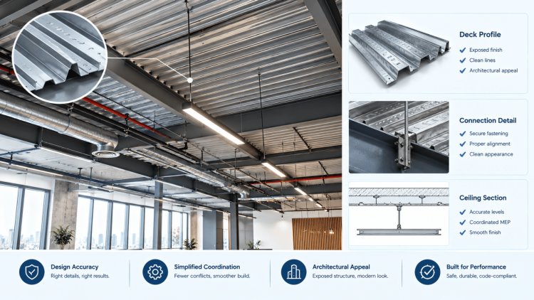
Exposed Architectural Deck Detailing
Why Exposed Deck Is a Different Detailing Discipline
Standard composite or roof deck detailing is engineered for concealment — paint overspray, insulation, and suspended ceilings mask imperfections. Exposed architectural deck removes that safety net entirely. Every sidelap condition, every puddle weld burn-through, every misaligned end lap becomes part of the finished visual language of the space. Understanding why this changes the detailing workflow is the essential first step.
Architectural Exposure Changes Expectations
Every Visible Deck Condition Becomes Part Of The Finished Appearance
Mill Finish vs. Prime Paint vs. Galvanized
Architectural exposure requires explicit finish specification on the structural drawings. Mill finish (bare cold-rolled) is economical but prone to surface rust before enclosure. A shop-applied prime coat provides a base for field-applied architectural paint. Galvanized deck offers superior corrosion resistance in humid or semi-exterior conditions such as covered parking or transitional canopies. Specify finish class and acceptable surface defect tolerances in the project specifications, not just on the plan notes.
Sidelap Fastening Visibility
Button-punch sidelap connections are the standard for concealed applications — they are fast and structurally adequate. However, button punches create a dimple on the exposed pan surface that is clearly visible under raking light. For exposed ceiling applications, screw sidelap fastening or arc-spot weld patterns should be evaluated. Coordinate fastener spacing with the deck manufacturer's load tables and document the approved method clearly in the structural notes to prevent field substitution.
End Lap Alignment & Tolerance
End laps over structural supports must be held to tighter tolerances in exposed applications. A misaligned end lap creates a shadow line perpendicular to the deck ribs that reads as a defect. Detail a minimum 2-inch end lap and specify alignment tolerance on the erection drawings. Consider specifying that end laps be located consistently — either all laps at mid-span bearings or all at beam centerlines — to create a deliberate, repeating pattern rather than a random defect distribution.
For a broader foundation on metal deck types and structural behavior, visit Consac's Deck Resource Library to review related technical articles before diving into exposed ceiling coordination.
Exposed Architectural Deck
Every Sidelap, Weld, Finish, And End Lap Becomes Part Of The Finished Visual Language Of The Space
Pourstop profiles, closure plates, fascia angles, and penetration edge trims all require explicit detailing that integrates structural, architectural, and sometimes curtain wall requirements simultaneously.
Detail 01
Pour-Stop & Perimeter Closure Details
Standard formed-steel pour stops are designed to retain concrete during composite slab pours. In exposed ceiling applications, the pour stop is also the visible terminus of the deck system at perimeter beams and walls. Specify a closure plate or architectural fascia angle to conceal the raw edge of the fluted deck pan.
Detail must account for
Structural beam flange width, deck bearing length, fireproofing requirements if applicable, and attachment method to the structural frame.
Exterior coordination
Coordinate with the exterior wall or curtain wall system to confirm the edge trim can be anchored without penetrating the air/water barrier.
Specify shop fabrication and prime coat for perimeter closure angles to match the deck finish specification. Field cutting and painting of closure angles in exposed applications produces inconsistent results that are difficult to correct after erection.
Detail 02
Deck Penetrations in the Exposed Field
Mechanical, electrical, and plumbing penetrations through exposed deck are among the most challenging coordination items. Unlike a concealed application where a rough cut can be patched above a drop ceiling tile, a penetration in an exposed deck ceiling is permanent and visible. Every penetration requires a shop-fabricated or precision field-cut reinforcing collar, a structural check for local load redistribution, and an architectural trim ring that closes the gap between the penetration edge and the passing element.
Detail penetration locations on a coordinated composite drawing that overlays structural deck layout, mechanical routing, and lighting fixture locations. Penetrations within 12 inches of a structural support require engineering review. Reference Consac’s Joist and Deck coordination articles for additional guidance on opening reinforcement strategies applicable to exposed conditions.
Never rely on field coordination alone for exposed deck penetrations—all penetration locations must be locked on the structural drawings before deck fabrication.
Detail 02
Deck Penetrations in the Exposed Field
Reinforcing collar
Shop-fabricated or precision field-cut.
Structural check
Confirm local load redistribution.
Architectural trim
Close the gap between penetration edge and passing element.
Detail 03
Lighting Pocket & Cove Integration
Recessed lighting pockets or cove lighting troughs integrated into the structural deck plane require framed openings with formed-steel headers, independent of the deck fluting pattern. Detail the header framing, the depth of the pocket relative to slab thickness, and the surface finish of the inside pocket faces.
Parallel to ribs
Pockets parallel to ribs are structurally simpler.
Perpendicular to ribs
Require more extensive header framing and should be reviewed by the structural engineer of record.
Detail 04
Expansion Joint Detailing
Building expansion joints bisecting an exposed deck ceiling field require a cover assembly that accommodates structure movement while maintaining a consistent ceiling plane appearance. Standard expansion joint covers designed for floor or roof applications are typically too heavy or produce an overly industrial profile.
Specify a lightweight aluminum or cold-formed steel cover that matches the deck finish, detail its attachment to allow free movement, and confirm with the structural engineer that the joint width and movement range are correctly represented in the architectural detail.
Detail 04
Expansion Joint Detailing
Cover material
Lightweight aluminum or cold-formed steel.
Attachment
Detail to allow free movement.
Structural confirmation
Confirm joint width and movement range.
Coordination requirement
Never rely on field coordination alone for exposed deck penetrations.
All penetration locations must be locked on the structural drawings before deck fabrication.
Coordination Protocols: Structural, Mechanical & Architectural Alignment
Exposed deck ceiling projects fail most often not from individual detailing errors but from coordination breakdowns between disciplines. The structural engineer details the deck for load capacity. The mechanical engineer routes ductwork assuming a concealed plenum. The architect specifies the deck finish without cross-referencing structural requirements. In an exposed application, all three must operate from a single coordinated model or composite drawing set from the earliest design phase — not during construction administration.
Schematic Lock
Fix structural grid, deck profile, finish class
Composite Coordination
Overlay MEP routing, penetrations, lighting
Detail Development
Draw perimeter, edge, and opening details
Shop Drawing Review
Check fabrication drawings against composite
Establishing this four-phase gate process early prevents the most costly category of exposed deck change orders: post-fabrication penetration additions and finish corrections. Document the coordination protocol in the project's design management plan and assign a single point of contact — typically the structural engineer or BIM manager — to own the composite overlay drawing throughout all phases.
Shop Drawing Review Standards
For exposed deck applications, shop drawing review must be elevated beyond a standard structural compliance check. The reviewing architect and structural engineer must jointly confirm that the fabricated deck profile, finish, fastener pattern, and accessory configurations match the project specifications. Any substitution proposed by the deck fabricator — including alternate sidelap fastener types or changed pour-stop profiles — must be evaluated for visual impact, not just structural equivalence. Establish this dual-review requirement explicitly in the submittal requirements section of the project specifications.
Field Inspection Checkpoints
Structural special inspection programs for composite decks rarely address the finish and aesthetic requirements of exposed applications. Supplement the standard structural inspection checklist with visual inspection hold points at:
1
Deck erection prior to any welding — check alignment, end laps, and panel condition.
2
After all arc-spot welds and sidelap fasteners are complete — inspect for burn-through, misalignment, and surface damage.
3
Before any field-applied coatings — confirm surface preparation meets the coating manufacturer's requirements for adhesion over the specified prime coat or galvanized surface.
RFI Management for Exposed Conditions
RFIs on exposed deck projects require faster and more thorough responses than standard structural RFIs because field-improvised solutions to exposed ceiling conditions are almost always visible and often irreversible. Establish an RFI response time limit of 48 hours for any item affecting the exposed deck ceiling plane, and require that all RFI responses include a sketch or annotated detail — not a narrative description alone.
For comprehensive detailing workflow strategies, the Consac Steel Joist Detailing blog series provides parallel protocols applicable to exposed structural systems.
Exposed Deck Ceiling Applications
Specification Language, Common Pitfalls & Takeaways
Even the most carefully developed details can be undermined by imprecise specification language. For exposed deck ceiling applications, specification sections 05 31 00 (Steel Deck) and 09 90 00 (Paints and Coatings) must be supplemented with project-specific requirements that address the exposed nature of the installation. Standard master specification language assumes concealment — it is the specifier's responsibility to augment it for visibility requirements.
Finish & Surface Defect Tolerances
Add explicit language defining acceptable surface defects for exposed deck panels. Reference the Steel Deck Institute (SDI) finish classifications and specify the maximum allowable size and frequency of surface marks, coil breaks, or minor dents. Include a mockup requirement — a minimum 4-foot by 8-foot erected panel mockup reviewed and approved by the architect before full fabrication release. This single requirement prevents the most common source of finish disputes on exposed deck projects.
Weld Appearance Requirements
Arc-spot welds (puddle welds) attach deck to structural framing and are fully visible in an exposed application. Standard structural specifications permit weld burns, splatter, and minor surface deformation that are structurally inconsequential but visually unacceptable. Specify maximum weld crown height, maximum weld splatter radius, and require that all visible welds be ground flush and touched up with a matching prime coat before field painting. Include these requirements in the structural specification section, not only in the architectural finishes section, so the deck contractor and structural inspector are both bound by them.
Sequence of Trades Requirement
Specify a required sequence of work that protects the exposed deck surface after erection.
Even the most carefully developed details can be undermined by imprecise specification language. For exposed deck ceiling applications, specification sections 05 31 00 (Steel Deck) and 09 90 00 (Paints and Coatings) must be supplemented with project-specific requirements that address the exposed nature of the installation.
Specification Requirements
Finish & Surface Defect Tolerances • Weld Appearance Requirements • Sequence of Trades Requirement