Form Deck Panelization Strategy for Repetitive Bays
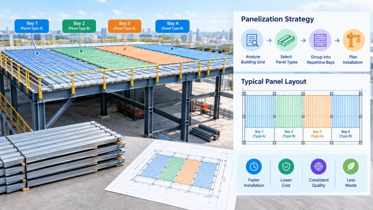
In repetitive-bay construction — parking structures, warehouse floors, multi-story residential, and light commercial framing — the efficiency of the entire project often hinges on a single upstream decision: how the form deck is panelized. A well-executed panelization strategy minimizes field cuts, reduces pour-strip waste, coordinates cleanly with shoring and re-shoring layouts, and feeds directly into fabrication and erection schedules. A poorly considered one creates cascading rework from the deck crew all the way through concrete placement. This guide addresses the structural and logistical mechanics of form deck panelization specific to repetitive bay geometries — the conditions where systematic, module-driven layout decisions deliver the greatest return. Topics covered include bay-width optimization relative to standard sheet lengths, orientation logic, end-lap and side-lap coordination, handling irregular bays at building edges, and translating panelization decisions into BIM
Why Panelization Decisions Matter More Than Most Teams Realize
Form deck panelization is frequently treated as a field-coordination problem — something the erection crew figures out once steel is in the air. In repetitive-bay projects, this assumption is costly. Because the same bay geometry repeats dozens or hundreds of times, any systematic inefficiency in the panel layout compounds at scale. A single unnecessary longitudinal cut per bay, across 80 bays, represents significant waste in material, labor hours, and schedule float.
The structural engineer and detailer are best positioned to make panelization decisions during the design and shop drawing phase, when bay dimensions, support spacing, and deck orientation can still be coordinated holistically.
The Compound Effect
Every inefficiency in panelization is multiplied by the number of repetitive bays. On a 100-bay parking structure, saving one unnecessary field cut per bay can recover 50–80 labor hours and eliminate 200–400 lf of wasted material.
Early panelization decisions made during the shop drawing phase cost virtually nothing to implement — but correcting them in the field after erection has begun can cost 3–5× the original savings in rework, schedule delay, and material replacement.
Treat panelization as a structural detailing decision, not a field coordination afterthought.
Any systematic inefficiency in panel layout compounds at scale. Resolve panelization during detailing, not after steel erection begins.
The most impactful panelization decision in a repetitive-bay project is the relationship between bay width, sheet length, and end-lap location. When these three variables are coordinated deliberately, the result is a layout where full sheets dominate the field and cuts are confined to predictable, manageable edge zones.
Form deck used as shoring-free formwork for one-way slabs typically spans between beams or joists. When the bay span exceeds available sheet lengths, an end-lap is required. SDI and manufacturer guidelines specify minimum end-lap lengths — commonly 2 in. for structural form deck, though project specs may require more to ensure bearing and continuity of concrete load transfer during placement.
In repetitive bays, the end-lap should be positioned consistently at the same location across all bays — ideally over a supporting beam or joist, not at mid-span. Locating end-laps over supports maximizes the structural efficiency of each sheet acting as a simple span element, reduces deflection under wet concrete load, and simplifies inspection since laps are accessible at the framing line.
When the bay dimension does not align with standard sheet lengths, the preferred resolution is to adjust the sheet length procurement rather than field-cut every sheet. A custom order of sheets at a non-standard length carries a modest upcharge but eliminates field cutting labor across the entire project run.
The following common sheet lengths should be evaluated against your bay dimension during early design. Targeting a length that produces a 0–3 in. overhang at the support, rather than a 12–18 in. cut, is the goal:
Typical for short-span applications and joisted bays with close spacing
Mid-range; most common in composite floor deck applications but applicable to form deck runs
Long-span form deck; requires verification of construction-stage deflection and shoring requirements
Available from select manufacturers; confirm lead time impact on schedule
Coordinate sheet length selection with your deck manufacturer's engineering department early — many offer free panelization review services that can validate span tables and end-lap requirements against your specific bay geometry and concrete thickness.
Bay-Width Optimization and Sheet Length Coordination
End-Lap Logic in Multi-Span Bays
Standard Sheet Length Reference
Selecting deck orientation is one of the most important layout decisions in a steel deck system. Orientation affects span behavior, load transfer, panelization efficiency, fastening requirements, erection sequencing, and construction-stage performance. The correct approach depends on framing arrangement, span geometry, and project-specific constructability objectives.
In this configuration, form deck sheets are installed with their long axis running parallel to the primary framing direction, with corrugated ribs also running parallel. Sheets bear perpendicularly across secondary framing members such as joists or secondary beams. This arrangement is the most common orientation for one-way slab systems utilizing closely spaced secondary framing.
Sheet lengths align efficiently with secondary framing spacing. Side-laps typically occur between framing members where attachment is straightforward. Edge terminations at primary beams remain consistent, simplifying detailing and installation.
End-lap locations must align with secondary support framing to prevent unsupported lap conditions. Construction-stage flexural capacity must be verified because wet concrete loads are carried across the short dimension of the deck sheet.
In this configuration, deck sheets span parallel to secondary framing while ribs run perpendicular to primary beam lines. Although less common for conventional form deck applications, it is frequently used in wide-bay systems where deck spans directly between primary beams or wall supports.
Secondary framing may be eliminated entirely, reducing steel tonnage and erection complexity. In repetitive structural bays, direct spanning can produce highly efficient panelization with fewer interior side-laps.
Longer spans require rigorous verification of construction loading capacity and service-stage deflection performance. Intermediate shoring is frequently required if spans exceed manufacturer limitations, potentially offsetting initial framing savings.
At building perimeters, stair and elevator cores, mechanical mezzanines, and re-entrant corners, maintaining the dominant field orientation is often impractical. Hybrid layouts preserve the primary orientation throughout the typical floor area while allowing perpendicular or angled panel configurations within irregular zones.
This strategy maximizes erection efficiency across the majority of the structure while accommodating geometric constraints at localized areas. By limiting orientation transitions to exceptional conditions, the detailing effort remains manageable and installation operations remain predictable.
Boundaries between orientation zones must be dimensioned clearly on panelization drawings. Sheet-cut locations, attachment requirements, transition framing, and edge fastening details should be explicitly identified because these areas consistently generate the highest concentration of field errors and RFIs.
Successful deck orientation strategy balances structural performance, constructability, material efficiency, and detailing simplicity. The most effective layouts maintain a consistent orientation throughout the typical field, introduce transitions only where geometry requires them, and fully document every boundary condition so installation crews can execute the design without ambiguity or field interpretation.
Deck Orientation Strategy: Parallel vs. Perpendicular to Primary Framing
Parallel Orientation
Perpendicular Orientation
Hybrid Orientation at Irregular Bays
Orientation Selection Guide
Layout Planning Principle
Even in the most regular repetitive-bay geometry, edge conditions at exterior walls, stair cores, column lines with varying spacing, and ramp transitions will require non-standard panel widths or lengths. The goal of a disciplined panelization strategy is not to eliminate field cuts entirely—it is to confine them to predictable zones and reduce their frequency in the typical field to near-zero.
Standardized trim zones, explicitly dimensioned cut panels, and pre-fabricated repetitive pieces reduce ambiguity, improve accuracy, and protect slab-edge quality.
Edge Conditions, Irregular Bays &
Field-Cut ManagementConfine field cuts to predictable zones—and drive their frequency in typical bays to near zero.
A panelization strategy is only as useful as its implementation in project documentation. For repetitive-bay projects operating in a BIM environment, the panelization plan must transition from a concept into a model-integrated, fabrication-ready deliverable. This requires deliberate coordination between the structural model, the steel detailer, and the deck fabricator.
For teams implementing BIM-based panelization workflows, Consac's structural deck modeling resources and the project coordination guides on the Digiverse Studio platform provide model setup templates and panel schedule examples aligned with current industry practice.
A well-documented panelization strategy, integrated into the BIM deliverable from the start, is the single highest-leverage investment a structural team can make on a repetitive-bay project.
Translating Panelization Strategy into BIM-Ready Documentation
What's Your Reaction?